Manual Manual 37223E 37223E easYgen-3000 easYgen-3000 Series Series (Package (Package P1) P1) - - Genset Genset ControlControl
© © Woodward Woodward Page Page 43/6743/67
Power MPower Measuringeasuring
≡≡≡≡≡≡≡≡≡≡≡≡≡≡≡≡≡≡≡≡≡≡≡≡≡
≡≡≡≡≡≡≡≡≡≡≡≡≡≡≡≡≡≡≡≡≡≡≡≡≡
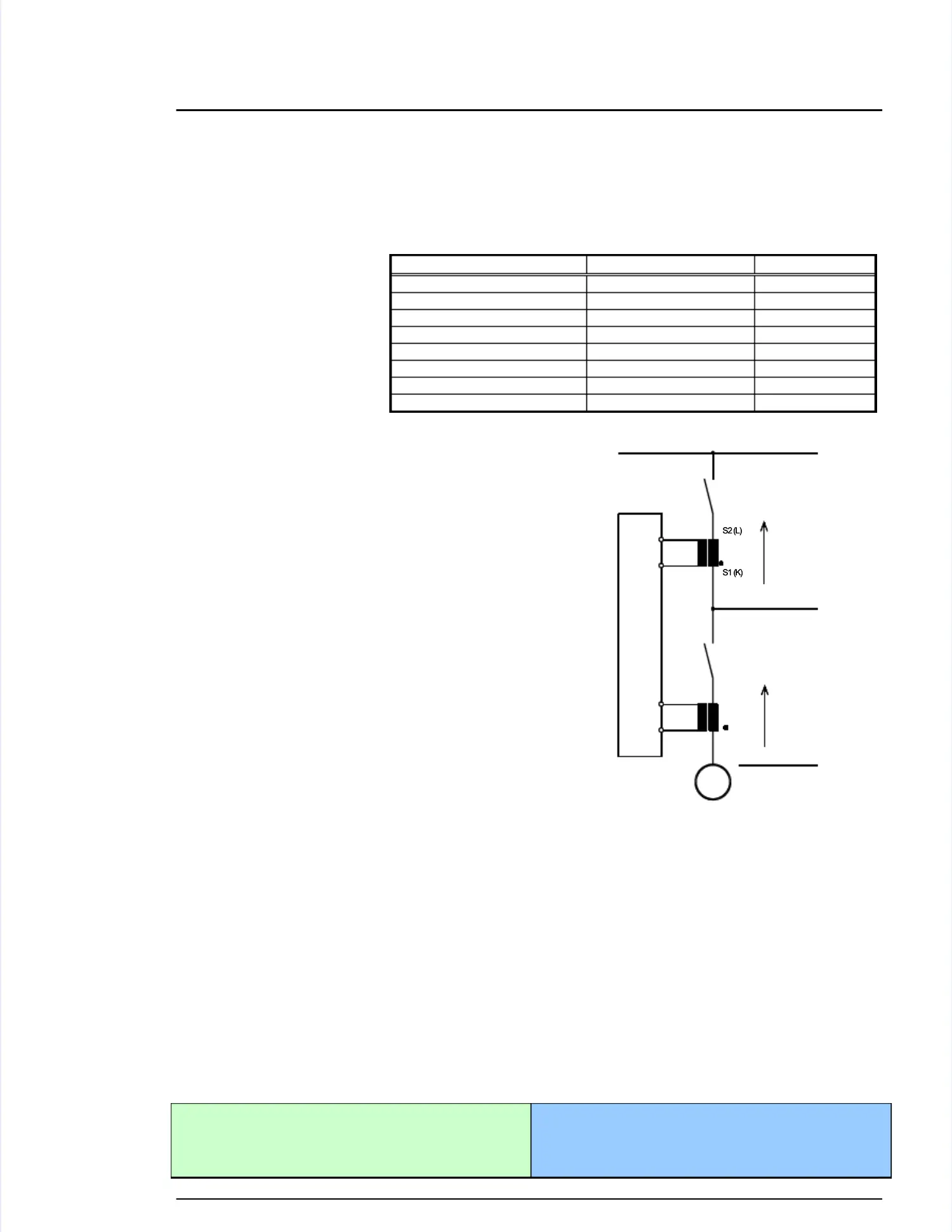
If the unit's current transformers are wired If the unit's current transformers are wired according to the diagram shown, the following values are displayed.according to the diagram shown, the following values are displayed.
Parameter Parameter Description Description Sign Sign displayeddisplayed
Generator Generator real real power power Genset Genset generating generating kW kW + + PositivePositive
Generator Generator real real power power Genset Genset in in reverse reverse power power - - NegativeNegative
Generator power factor (cos φ)Generator power factor (cos φ) Inductive Inductive / / lagging lagging + + PositivePositive
Generator power factor (cos φ)Generator power factor (cos φ)
Capacitive Capacitive / / leading leading - - NegativeNegative
Mains Mains real real power power Plant Plant exporting exporting kW kW + + + + PositivePositive
Mains Mains real real power power Plant Plant importing importing kW kW - - - - NegativeNegative
Mains power factor (cos φ)Mains power factor (cos φ) Inductive Inductive / / lagging lagging + + PositivePositive
Mains power factor (cos φ)Mains power factor (cos φ) Capacitive Capacitive / / leading leading - - NegativeNegative
S1 (K)S1 (K)
S2 (L)S2 (L)
S2 (L)S2 (L)
S1 (K)S1 (K)
Real powerReal power
display positivedisplay positive
Reacitive powerReacitive power
display inductivedisplay inductive
Real powerReal power
display positivedisplay positive
Reacitive powerReacitive power
display inductivedisplay inductive
GCGCBB
generator circuit breakergenerator circuit breaker
MMCBCB
mains circuit breakermains circuit breaker
ee
aa
ss
YY
gg
ee
nn
66
55
s1 (k)s1 (k)
GG
s2 (l)s2 (l)
22
11
s1 (k)s1 (k)
s2 (l)s2 (l)
poposs
poposs
GENERATORGENERATOR
indindindind
QQQQ
PPPP
poposs
poposs
indind
QQQQ
PPPP
BUSBARBUSBAR
MAINSMAINS
Figure 6-37: Power measuring - directiFigure 6-37: Power measuring - direction of poweron of power
Power Factor DefinitionPower Factor Definition
≡≡≡≡≡≡≡≡≡≡≡≡≡≡≡≡≡≡≡≡≡≡≡≡≡
≡≡≡≡≡≡≡≡≡≡≡≡≡≡≡≡≡≡≡≡≡≡≡≡≡
The phasor diagram is used from the generator's view. PoThe phasor diagram is used from the generator's view. Power factor is defined as follows.wer factor is defined as follows.
Power Factor is defined as a ratio of the real power to apparent power. In a purely resistive circuit, the voltagePower Factor is defined as a ratio of the real power to apparent power. In a purely resistive circuit, the voltage
and current waveforms are instep resulting in a ratio or power factor of 1.00 (often referred to as unity). In an in-and current waveforms are instep resulting in a ratio or power factor of 1.00 (often referred to as unity). In an in-
ductive circuit the current lags behind the ductive circuit the current lags behind the voltage waveform resulting in usable power (real power) and unusablevoltage waveform resulting in usable power (real power) and unusable
power (reactive power). This results in a positive ratio or lagging power factor (i.e. power (reactive power). This results in a positive ratio or lagging power factor (i.e. 0.85lagging). In a capacitive0.85lagging). In a capacitive
circuit the current waveform leads the voltage waveform resulting in usable power (real circuit the current waveform leads the voltage waveform resulting in usable power (real power) and unusablepower) and unusable
power (reactive power). This results in a negative ratio or a leading power factor (i.e. power (reactive power). This results in a negative ratio or a leading power factor (i.e. 0.85leading).0.85leading).
Inductive: Electrical load whose current waveform lagsInductive: Electrical load whose current waveform lags
the voltage waveform thus having a lagging power the voltage waveform thus having a lagging power fac-fac-
tor. Some inductive loads such as electric tor. Some inductive loads such as electric motors have amotors have a
large startup current requirement resulting in llarge startup current requirement resulting in laggingagging
Capacitive: Electrical load whose current waveformCapacitive: Electrical load whose current waveform
leads the voltage waveform thus having a leads the voltage waveform thus having a leading powerleading power
factor. Some capacitive loads such as capacitor bfactor. Some capacitive loads such as capacitor banksanks
or buried cable result in leading power factors.or buried cable result in leading power factors.
 Loading...