ZC702 Board User Guide www.xilinx.com 13
UG850 (v1.7) March 27, 2019
Electrostatic Discharge Caution
5
J64 SD Card Interface connector
Molex 67840-8001 SDIO Memory card
connector
22
6
U23
Programmable Logic JTAG
Programming Options with integrated
Micro-B connector
Digilent USB JTAG Module 15
7
U43
System Clock, 200 MHz, 2.5V LVDS
oscillator
SiTime SIT9102-243N25E200.0000 30
8
U28, U65
Programmable User Clock and
Processing System Clock Source
Silicon Labs SI570BAB0000544DG, default
156.250MHz, PS fixed 33 MHz clock
30
9
U35, P2
10/100/1000 MHz Tri-Speed Ethernet
PHY, RJ45 w/magnetics
Marvell 88E1116RA0-NNC1C000, Halo
HFJ11-1G01ERL
25
–26
10
X1
Ethernet PHY Clock Source,
25.000 MHz
Epson MA-506-25.000m-CO:ROHS 25
11
DS6
–DS8
Ethernet PHY User LEDs Ethernet PHY User LEDs, GREEN 25
12
U36, J17
USB-to-UART Bridge, USB Mini-B
connector
Silicon Labs CP2103GM, Molex 54819-0589 36
13
U40, P1 HDMI Video Output
Analog Devices ADV7511KSTZ-P HDMI
transmitter, Molex 500254-1927 HDMI
receptacle
28
–29
14 U44 I2C Bus TI PCA9548ARGER 32
15 U16 Real-Time Clock Epson RTC-8564JE:3:ROHS 33
16
J54
I/O Expansion Header driven from I2C
Expander U80
2-row pin header 33
17 DS15–DS22 User LEDs GPIO LEDs, GREEN 0603 34
18
SW5, SW7
User Pushbuttons SW5 = Left, SW7 =
Right
E-Switch TL3301EP100QG 34
19 SW12 GPIO DIP Switch 2-pole C&K SDA02H1SBD 34
20 SW11 Power On/Off Slide Switch C and K 1201M2S3AQE2 47
21 U14 High Speed CAN Transceiver NXP TJA1040T/VM 21
22 SW4 Program_B Pushbutton E-Switch TL3301EP100QG 34
23
SW10, J2
Programmable Logic JTAG Select
Switch, JTAG Cable Connector
2-pole C and K SDA02H1SBD
MOLEX 87832-1420
15
24 J3, J4 FPGA Mezzanine (FMC) Card Interface Samtec ASP_134486_01 23, 24
25
U32, U33, U34
Power Management (bottom and top
of board)
TI UCD9248PFC in conjunction with various
regulators
39
–47
26 J40 XADC Analog-to-Digital Converter 2X10 0.-inch male header 31
27
SW1, SW2
PS Power-On and System Reset
Pushbuttons
Panasonic EVQ-11L07K 14 35, 36
28
J62, J63 User PMOD GPIO Headers
J63 2 x 6 0.1 inch J63 1 x 6 0.1 inch male
headers
34, 35
29
SW16 5-pole SPDT MIO DIP switch
CTS 206-125. See Table 1-2 for switch
settings.
14
30
J59
2x5 shrouded PMBus connector
(bottom of board)
ASSMAN HW10G-0202 47
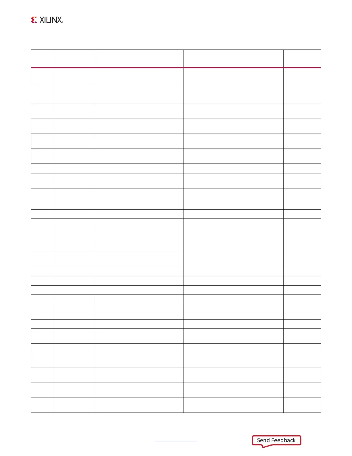
Table 1-1: ZC702 Board Component Descriptions (Cont’d)
Callout
Reference
Designator
Component Description Notes
Schematic
(1)
0381449 Page
Number

 Loading...


