ZC702 Board User Guide www.xilinx.com 21
UG850 (v1.7) March 27, 2019
Feature Descriptions
Note: The ZC702 DDR3 4x 8-bit component memory interface adheres to the constraints guidelines
documented in the DDR3 Design Guidelines section of the 7 Series FPGAs Memory Interface Solutions
v1.8 User Guide (UG586) [Ref 4]. The ZC702 DDR3 memory interface is a 40
Ω impedance
implementation. Other memory interface details are available in UG586 and the 7SeriesFPGAs
Memory Resources User Guide (UG473) [Ref 5]. For more details, see the Micron MT41J256M8HX-15E
data sheet at the Micron website [Ref 14].
Quad-SPI Flash Memory
[Figure 1-2, callout 3]
The Quad-SPI flash memory located at U41 provides 128 Mb of non-volatile storage that
can be used for configuration and data storage.
• Part number: N25Q128A11ESF40G (Micron)
• Supply voltage: 1.8V
• Datapath width: 4 bits
• Data rate: Various depending on Single/Dual/Quad mode
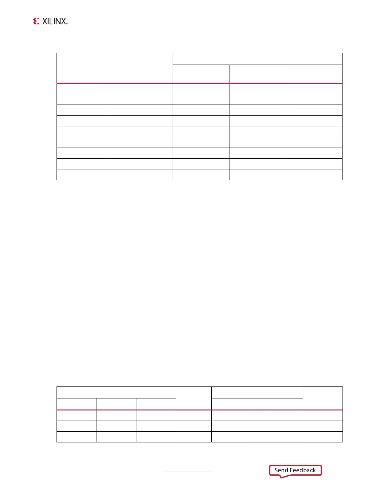
The connections between the SPI flash memory and the XC7Z020 SoC are listed in
Table 1-5.
P3
PS_DDR3_CAS_B
G3 CAS_B U66, U67, U68, U69
R5
PS_DDR3_RAS_B
F3 RAS_B U66, U67, U68, U69
F3
PS_DDR3_RESET_B
N2 RESET_B U66, U67, U68, U69
P6
PS_DDR3_CS_B
H2 CS_B U66, U67, U68, U69
P5
PS_DDR3_ODT
G1 ODT U66, U67, U68, U69
M7
PS_VRN
N7
PS_VRP
H7
VTTVREF_PS
P7
VTTVREF_PS
Table 1-5: Quad SPI Flash Memory Connections to the XC7Z020 SoC
XC7Z020 (U1)
Schematic
Net Name
Quad-SPI Flash Memory (U41)
MIO Select
Header
Pin Name Bank Pin Number Pin Number Pin Name
PS_MIO6 500 A4 QSPI_CLK
16 C J26.2
PS_MIO5 500 A3 QSPI_IO3
1 DQ3_HOLD_B J25.2
PS_MIO4 500 E4 QSPI_IO2
9 WP_B J22.2
Table 1-4: DDR3 Component Memory Connections to the XC7Z020 SoC (Cont ’d)
XC7Z020 (U1) Pin Net Name
Component Memory
Pin Number Pin Name
Reference
Designator

 Loading...


