ZC702 Board User Guide www.xilinx.com 44
UG850 (v1.7) March 27, 2019
Feature Descriptions
Ethernet PHY User LEDs
[Figure 1-2, callout 11]
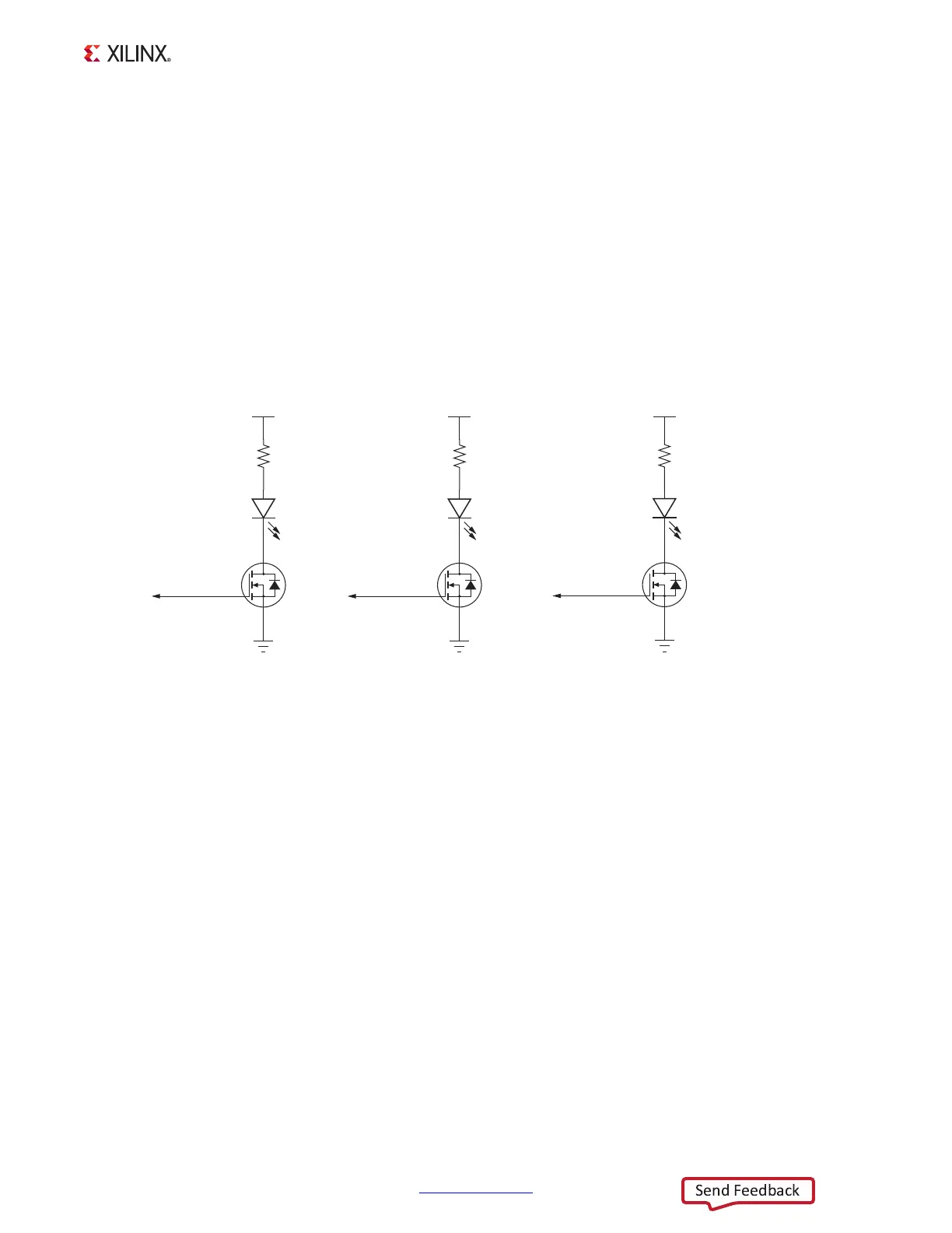
The three Ethernet PHY user LEDs shown in Figure 1-20 are located near the RJ45 Ethernet
jack P2. The on/off state for each LED is software dependent and has no specific meaning at
Ethernet PHY power on.
Refer to the Marvell 88E1116R Alaska Gigabit Ethernet transceiver data sheet for details
concerning the use of the Ethernet PHY user LEDs. They are referred in the data sheet as
LED0, LED1, and LED2. The data sheet and other product information for the Marvell
88E1116R Alaska Gigabit Ethernet Transceiver is available at the Marvell website [Ref 20].
User I/O
[Figure 1-2, callout 17–28]
The ZC702 board provides the following user and general purpose I/O capabilities:
• Ten user LEDs (callout 17)
°
PMOD0 0–PMOD0 3 and PMOD1 0–PMOD1 3: DS15–DS22
°
PS_LED1: DS23 and PS_MIO8_LED0: DS12
• Two user pushbuttons and reset switch (callout 18)
°
GPIO_SW_N and GPIO_SW_S: SW5 and SW7
• 2-position user DIP switch (callout 24)
°
GPIO_DIP_SW1 and GPIO_DIP_SW0: SW12
• User PS switches (near callout 18)
X-Ref Target - Figure 1-20
Figure 1-20: Ethernet PHY User LEDs
UG850_c1_20_032719
1
3
2
Q7
NDS331N
460 mW
DS6
VCC3V3
PHY LED 2
1
3
2
Q9
NDS331N
460 mW
DS8
VCC3V3
PHY LED 0
318
261
0.1Ω
1
3
2
Q8
NDS331N
460 mW
DS7
VCC3V3
PHY LED1
317
261
0.1Ω
GNDGNDGND
316
261
0.1Ω

 Loading...


