ZC702 Board User Guide www.xilinx.com 64
UG850 (v1.7) March 27, 2019
Feature Descriptions
Table 1-33 defines the voltage and current values for each power rail controlled by the
UCD9248 PMBus controller at address 54 decimal (U34).
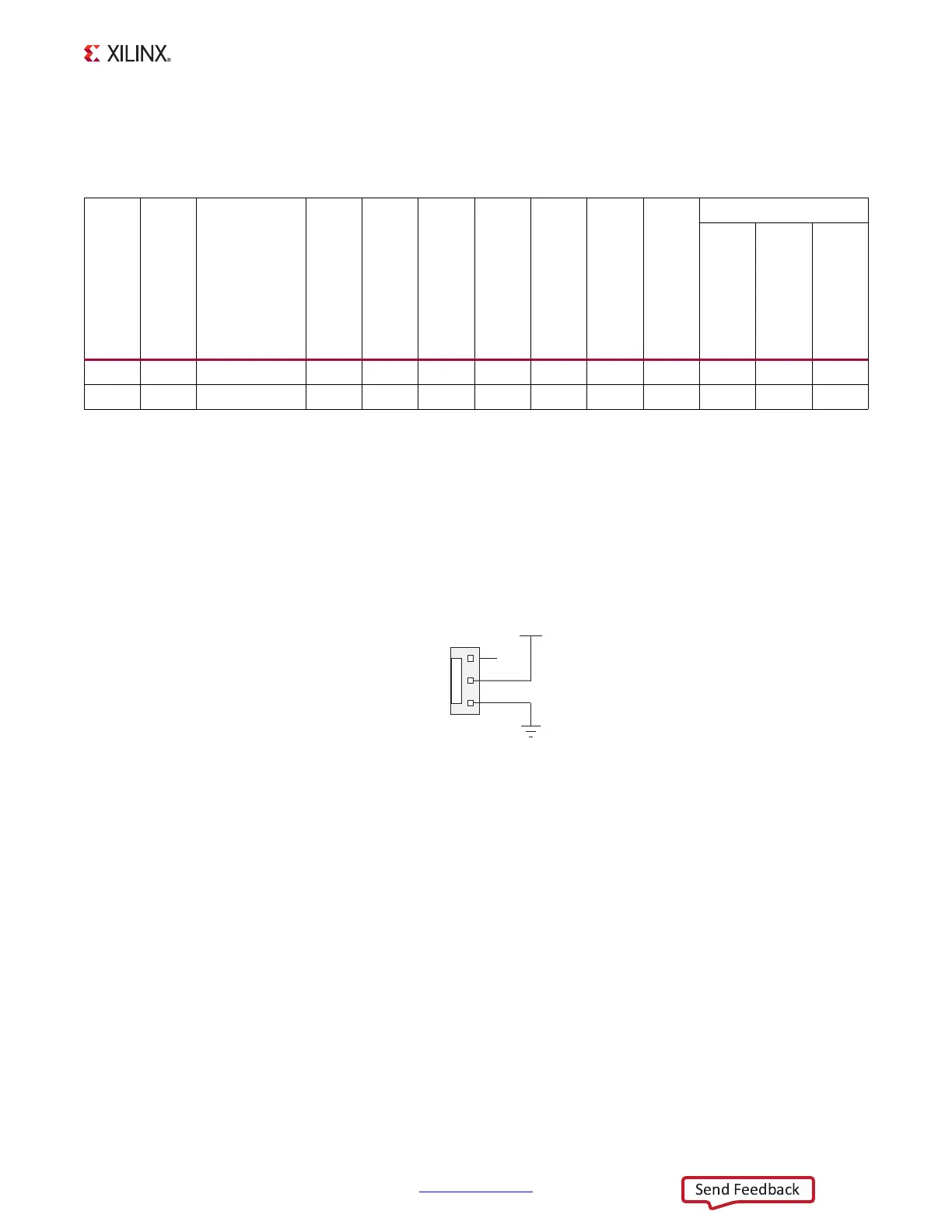
Cooling Fan
The XC7Z020 SoC cooling fan connector J61 is wired directly to 12V
DC
as shown in
Figure 1-30.
More information about the power system components used by the ZC702 board are
available from the Texas Instruments digital power website [Ref 25].
Table 1-33: Power Rail Specifications for UCD9248 PMBus Controller at Address 54 Decimal
Shutdown Threshold
(1)
Rail
Number
Rail
Name
Schematic
Rail Name
Nominal VOUT (V)
PG
On Threshold (V)
PG
Off Threshold (V)
On Delay (ms)
Rise Time (ms)
Off Delay (ms)
Fall Time (ms)
VOUT Over Fault (V)
IOUT Over Fault (A)
Temp Over Fault (°C)
1 Rail #1 VCC3V3 3.3 2.97 2.805 0 5 4 1 3.795 10.41 90
2 Rail #2 VCC2V5 2.5 2.25 2.125 0 5 1 1 2.875 10.41 90
Notes:
1. The values defined in these columns are the voltage, current, and temperature thresholds that causes the regulator to shut
down if the value is exceeded.
X-Ref Target - Figure 1-30
Figure 1-30: Cooling Fan Circuit
1
2
3
J61
GND
VCC12_P
UG850_c1_30_030513
NC

 Loading...


