ZC702 Board User Guide www.xilinx.com 63
UG850 (v1.7) March 27, 2019
Feature Descriptions
internally OR's these PG conditions together and drives an output PG pin High only if all
active rail PG states are “good”. The On and Off Delay and rise and fall times are relative to
when the board power on-off slide switch SW12 is turned on and off.
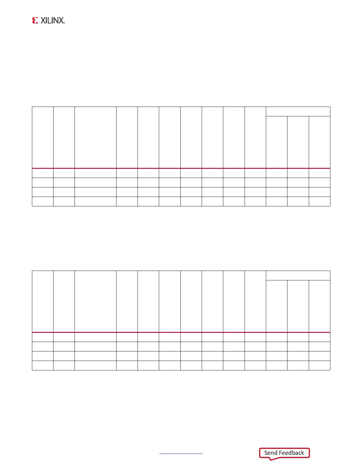
Table 1-31 defines the voltage and current values for each power rail controlled by the
UCD9248 PMBus controller at address 52 decimal (U32).
Table 1-32 defines the voltage and current values for each power rail controlled by the
UCD9248 PMBus controller at address 53 decimal (U33).
Table 1-31: Power Rail Specifications for UCD9248 PMBus Controller at Address 52 Decimal
Shutdown Threshold
(1)
Rail
Number
Rail
Name
Rail Name
Nominal VOUT (V)
PG
On Threshold (V)
PG
Off Threshold (V)
On Delay (ms)
Rise Time (ms)
Off Delay (ms)
Fall Time (ms)
VOUT Over Fault (V)
IOUT Over Fault (A)
Temp Over Fault (°C)
1 Rail #1 VCCINT 1 0.9 0.85 0 5 10 1 1.15 20 90
2 Rail #2 VCCPINT 1 0.9 0.85 0 5 10 1 1.15 20 90
3 Rail #3 VCCAUX 1.8 1.62 1.53 0 5 5 1 2.07 10.41 90
4 Rail #4 VCCPAUX 1.8 1.62 1.53 0 5 5 1 2.07 10.41 90
Notes:
1. The values defined in these columns are the voltage, current, and temperature thresholds that causes the regulator to shut
down if the value is exceeded.
Table 1-32: Power Rail Specifications for UCD9248 PMBus Controller at Address 53 Decimal
Shutdown Threshold
(1)
Rail
Number
Rail
Name
Schematic
Rail Name
Nominal VOUT (V)
PG
On Threshold (V)
PG
Off Threshold (V)
On Delay (ms)
Rise Time (ms)
Off Delay (ms)
Fall Time (ms)
VOUT Over Fault (V)
IOUT Over Fault (A)
Temp Over Fault (°C)
1 Rail #1 VADJ 2.5 2.25 2.125 0 5 1 1 2.875 10.41 90
2 Rail #2 VCC1V5 1.5 1.35 1.275 0 5 0 1 1.725 10.41 90
3 Rail #3 VCCMIO_PS 1.8 1.62 1.53 0 5 5 1 2.07 10.41 90
4 Rail #4 VCCBRAM 1 0.9 0.85 0 5 10 1 1.15 20 90
Notes:
1. The values defined in these columns are the voltage, current, and temperature thresholds that causes the regulator to shut
down if the value is exceeded.

 Loading...


