ZCU104 Board User Guide 67
UG1267 (v1.1) October 9, 2018 www.xilinx.com
Chapter 3: Board Component Descriptions
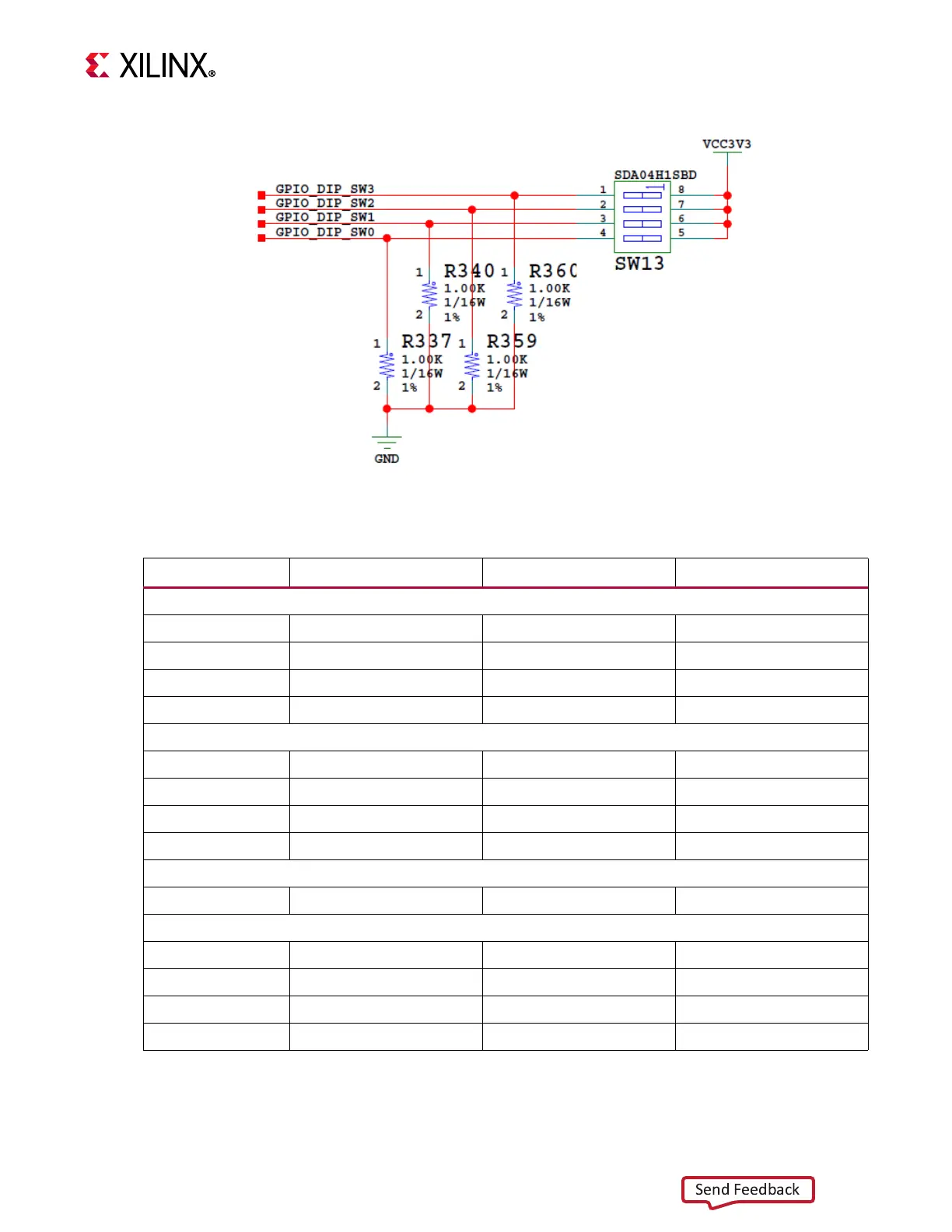
X-Ref Target - Figure 3-24
Figure 3-24: GPIO 8-Pole DIP Switch
Table 3-24: XCZU7EV U1 to GPIO Connections
XCZU7EV (U1) Pin Net Name I/O Standard Device
GPIO LEDs (Active High)
(1)
D5 GPIO_LED_0 LVCMOS33 DS38.2
D6 GPIO_LED_1 LVCMOS33 DS37.2
A5 GPIO_LED_2 LVCMOS33 DS39.2
B5 GPIO_LED_3 LVCMOS33 DS40.2
Directional Pushbuttons (Active High)
B4 GPIO_PB_SW0 LVCMOS33 SW14.3
C4 GPIO_PB_SW1 LVCMOS33 SW15.3
B3 GPIO_PB_SW2 LVCMOS33 SW17.3
C3 GPIO_PB_SW3 LVCMOS33 SW18.3
CPU Reset Pushbutton (Active High)
M11 CPU_RESET LVCMOS33 SW20.3
GPIO DIP SW (Active High)
E4 GPIO_DIP_SW0 LVCMOS33 SW13.8
D4 GPIO_DIP_SW1 LVCMOS33 SW13.7
F5 GPIO_DIP_SW2 LVCMOS33 SW13.6
F4 GPIO_DIP_SW3 LVCMOS33 SW13.5
Notes:
1. LEDs are driven through the U163 SN74AVC4T245 buffer.

 Loading...


