14
Rear Panel
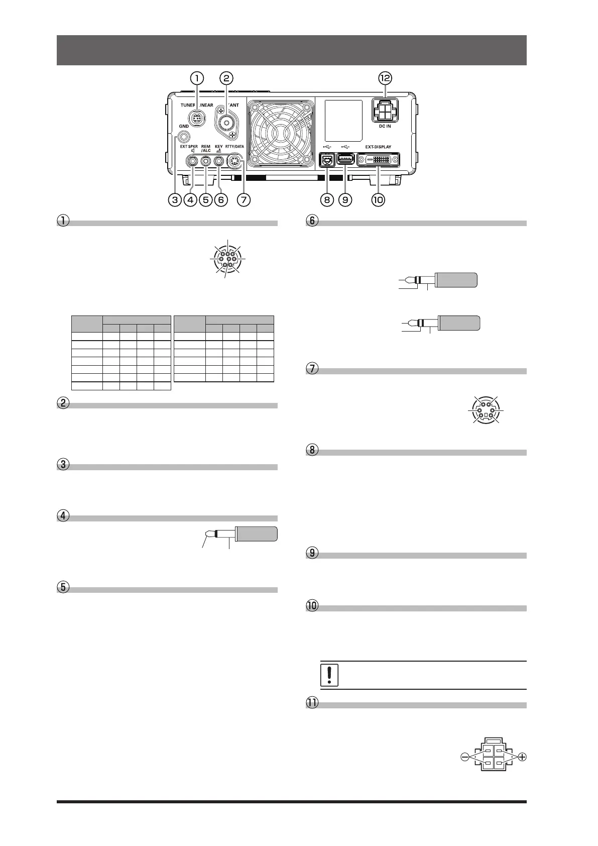
TUNER/LINEAR
This 8-pin output
jack is used to con-
nect to the FC-40
External Automatic
Antenna Tuner or a
Linear Amplier.
Refer to the table below for the BAND DATA termi-
nal levels when using a linear amplier.
BAND
BAND DATA
BAND
BAND DATA
A B C D A B C D
400k H L H H 18 L H H L
1 L H H H 21 H H H L
1.8 H L L L 24.5 L L L H
3.5 L H L L 28 H L L H
5 / 7 H H L L 50 L H L H
10 L L H H 70 H H H H
14 H L H L
ANT
Connect the main antenna here, using type-M (PL-
259) connectors and coaxial feed lines. The internal
antenna tuner aects only the antenna connected
here, and only during transmission.
GND
Use this terminal to connect the transceiver to a
good earth ground, for safety and optimal perfor-
mance.
EXT SPKR
This 3.5-mm, 2-contact, jack
provides audio output for a
supplied external loudspeak-
er “SP-40”. The impedance
at the jack is 4-8 Ohms.
REM/ALC
By plugging the FH-2 Remote Control Keypad into
this jack, direct access to the FT-710 CPU is pro-
vided for control functions of the contest memory
keying, and also frequency and function control.
When a device such as a linear amplifier is con-
nected, this is an external ALC current input jack.
KEY
This 3.5-mm, 3-contact jack accepts a CW key or
keyer paddle. A two-contact plug cannot be used
in this jack. Key-up voltage is +5.0V DC, and key-
down current is 3mA.
KEY
NC
When connecting a single straight key
DOT
DASH
When connecting an electronic keyer paddle
RTTY/DATA
This 6-pin input/output jack accepts AFSK input
from a Terminal Node
Controller (TNC); it also
provides xed level receiv-
er audio output, and FSK
keying line.
USB
Connecting to a computer from this jack with a
commercially available USB cable allows remote
control by CAT commands from a computer. The
jack can also be used for input and output of audio
signals and transmitter control. A USB driver is re-
quired for remote control from a computer. Down-
load the driver from the Yaesu website (http://www.
yaesu.com).
USB Jack
Connect a USB A type keyboard or mouse. They
can be used to select items on the screen or to en-
ter characters.
EXT-DISPLAY
DVI-D connector for connecting an external moni-
tor.
When using an external monitor, set the setting
menu item “EXT DISPLAY” to “ON”.
Connect a monitor that supports 800 x 480
resolution or 800 x 600 resolution.
DC IN
This is the DC power supply connection for the
transceiver.
Use the supplied DC cable to
connect directly to a DC power
supply, which must be capable
of supplying at least 25 A @13.8
VDC.
PTT SHIFT
TX INH BAND C
TX GND
GND
 Loading...