2
Table of Contents
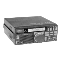
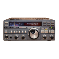
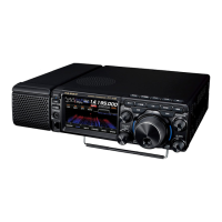
General Description ........................................ 4
Safety Precautions .........................................6
Accessories & Options ...................................8
Installation and Interconnections ....................9
Antenna Considerations ..................................... 9
Antenna Connections ......................................... 9
Power Cable Connections .................................. 9
Microphone, Headphone, Key, Keyer and
FH-2 Connections ............................................ 10
Linear Amplier Interconnections ..................... 11
VL-1000 Linear Amplier Interconnections .... 11
Display connections ......................................... 12
Remote operation (LAN unit “SCU-LAN10”)
connection ........................................................ 12
AESS (Acoustic Enhanced
Speaker System) ..........................................13
SP-40 connections ........................................... 13
Rear Panel....................................................14
TUNER/LINEAR ....................................... 14
ANT ........................................................... 14
GND .......................................................... 14
EXT SPKR ................................................ 14
REM/ALC .................................................. 14
KEY........................................................... 14
RTTY/DATA .............................................. 14
USB .......................................................... 14
USB Jack .................................................. 14
EXT-DISPLAY ........................................... 14
DC IN ........................................................ 14
SSM-75E Microphone Switches ...................15
Display Indications........................................16
Meter Display ............................................ 17
Operation MODE Display ......................... 17
Operation status Display .......................... 17
HI-SWR Display ........................................ 17
Frequency Display (VFO-A) ..................... 18
Keyboard Frequency Entry ...................... 18
Tuning in 1 MHz or 1 kHz Steps ............... 18
Frequency Display (VFO-B) ..................... 18
When the clarier function is active .......... 18
Operation of the display [FUNC] knob ...... 19
Filter Function Display .............................. 20
Turn the spectrum display OFF ................ 20
Information displayed on the
scope screen ............................................ 20
Important Receiver Settings ..................... 21
ATT (Attenuator) ....................................... 21
IPO ........................................................... 21
DNF (Digital NOTCH Filter) ...................... 21
AGC (Automatic Gain Control) ................. 21
Information displayed on
the scope screen ...................................... 22
Scope Display Setting .............................. 22
CENTER/CURSOR/FIX ........................... 22
CENTER................................................... 22
CURSOR .................................................. 22
FIX ............................................................ 23
3DSS ........................................................ 23
MULTI ....................................................... 23
EXPAND ................................................... 24
SPAN ........................................................ 24
SPEED ..................................................... 24
Set with the FUNC knob ........................... 25
LEVEL ...................................................... 25
PEAK ........................................................ 25
MARKER .................................................. 26
COLOR..................................................... 26
Adjust contrast.......................................... 26
Adjusting the brightness (DIMMER) ......... 26
Other display settings ........................................ 27
Screen Saver ................................................. 27
Inputting the Call Sign ................................... 27
Front Panel Controls & Switches .................. 30
ON/OFF (LOCK) Switch ........................... 30
SD memory card slot ................................ 30
TUNE ........................................................ 30
VOX/MOX ................................................. 30
Adjusts the VOX GAIN ............................. 30
Adjusts the VOX Delay Time .................... 30
Adjusts the VOX anti-trip sensitivity ......... 31
PHONES Jack .......................................... 31
MIC ........................................................... 31
MAIN dial .................................................. 31
WIRE STAND ........................................... 31
STEP
•
MCH /
............................... 32
DSP interference removal functions ......... 32
1. SHIFT ................................................... 33
2. WIDTH.................................................. 33
3. NOTCH................................................. 33
4. CONTOUR ........................................... 34
Adjusting the GAIN of the
CONTOUR Circuit ................................ 34
Sets the Bandwidth (“Q”) of the
CONTOUR Circuit ................................ 34
5. APF....................................................... 34
DSP RESET ............................................. 34
DNR (Digital Noise Reduction) ................. 35
Adjusting the DNR Level ........................... 35
A/B ............................................................ 35
BAND (
Operating Band Selection
) ................ 35
QMB (Quick Memory Bank) ...................... 35
QMB Channel Storage ............................. 35
QMB Channel Recall ................................ 35
Changing the number of QMB channels .. 35
VMI (VFO mode indicator) ........................ 36
BUSY/TX indicator .................................... 36
NAR (Narrow) ........................................... 36
FINE/FAST................................................ 36
RF GAIN/SQL ........................................... 37
Switching the operation of the
[RF GAIN/SQL] knob ................................ 37
 Loading...