4
General Description
SDR receiver circuit designed with emphasis on fundamental performance
The high-resolution A/D converter and the FPGA element developed for the high-end SDR Yaesu Trans-
ceivers are utilized. The twin A/D converter circuit conguration performs digital conversion processing
using two A/D converters and FPGA digital synthesis. A/D converter overow due to overload is reduced
to improve blocking characteristics. In addition, random noise is added to the analog signal before digital
conversion, and by minimizing the quantization error during digital conversion by the A/D converter, distor-
tion is suppressed. Then Dithering technology is implemented to improve IM (intermodulation) character-
istics, etc., and enhance the overall performance of the SDR receiver circuit.
3DSS method adopted
In addition to the conventional waterfall display, a 3DSS (3 Dimensions Spectrum Stream) image method
has been adopted. The 3DSS image uses the horizontal axis (X axis) for frequency, the vertical axis (Y
axis) for signal intensity, and the Z axis for time. Compared to the conventional waterfall method, the sig-
nal strength is displayed in three dimensions as well as in color, recognition of changes in the band condi-
tions is instant, convenient and intuitive.
AESS (Acoustic Enhancement Speaker System) produces high-delity Audio
Using DSP signal processing, the speaker in the top of the Transceiver, and an external side speaker are
combined to reproduce high-quality received audio with a wide frequency range and a three-dimension-
al eect that would not be expected from a compact HF transceiver. set the optimum sound quality by
adjusting the output balance and frequency characteristics of the two speakers according to your prefer-
ence.
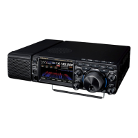
High-brightness TFT full-color display with touch-panel functionality
The FT-710 is equipped with a 4.3-inch full-color TFT display. Operating functions, including the receiving
band noise and signal interference reduction tools, are graphically displayed. Even while involved in rig-
orous operations, such as DXpeditions and contests, the operator may instantly grasp the status of each
function.
Filter Function Display monitors the status of the passband
In the upper part of the display, a lter function display presents the state of the pass-band. In addition to
the operating state of the interference removal functions, the lter function information is displayed. Not
only can you grasp the operating status of WIDTH, SHIFT, NOTCH and CONTOUR at a glance, you can
also view the status of the RF spectrum in the passband.
Two selectable RF Stages amplify the desired signals from low band to
high band
RF amplifier AMP1, and AMP2 are low noise negative feedback RF amplifiers that may be selected or
combined in series as is needed for various low-band, high-band, frequency and noise conditions.
In addition, the IPO (Intercept Point Optimization) function maximizes the dynamic range and enhances
the close multi-signal and inter-modulation characteristics of the receiver. The inuence of strong broad-
casting stations, especially in the low bands, can be minimized.
WIDTH and the continuously variable Bandwidth SHIFT features per-
mit elimination of interfering signals
The WIDTH feature allows the bandwidth to be narrowed by rotating the WIDTH knob. The SHIFT feature,
can eliminate interference in one side of the passband. Often, weak signals disappear due to interfering
signals (including pile-ups). The interfering signals may be extracted, leaving only the desired signal, be-
cause of the unique DSP sharp ltering characteristics.
CONTOUR feature is renowned for eective noise reduction
Rather than using the DSP extremely sharp attenuation characteristics, the CONTOUR circuit provides
gentle shaping of the DSP passband lter, and can thus attenuate or peak bandwidth components in seg-
ments. The interfering signal can be naturally shaped without having part of the signal suddenly disrupted.
The contour function is very eective in making the desired signal rise out of the interference.
 Loading...