33
1. SHIFT
1. Press the [STEP • MCH /
] knob.
2. Rotate the [STEP •MCH/
] knob to select
“SHIFT”, then press the [STEP • MCH /
] knob.
(The function may also be selected by touching
“SHIFT”.)
The shift frequency blinks.
3. Rotate the [STEP • MCH /
] knob to the left or
right to reduce interfering signals.
4. Press the [STEP •MCH /
] knob, then press
the [DSP RESET] key or wait for about 5 seconds to
save the setting.
Press and hold the [STEP • MCH /
] knob to
quickly move the lter passband to center.
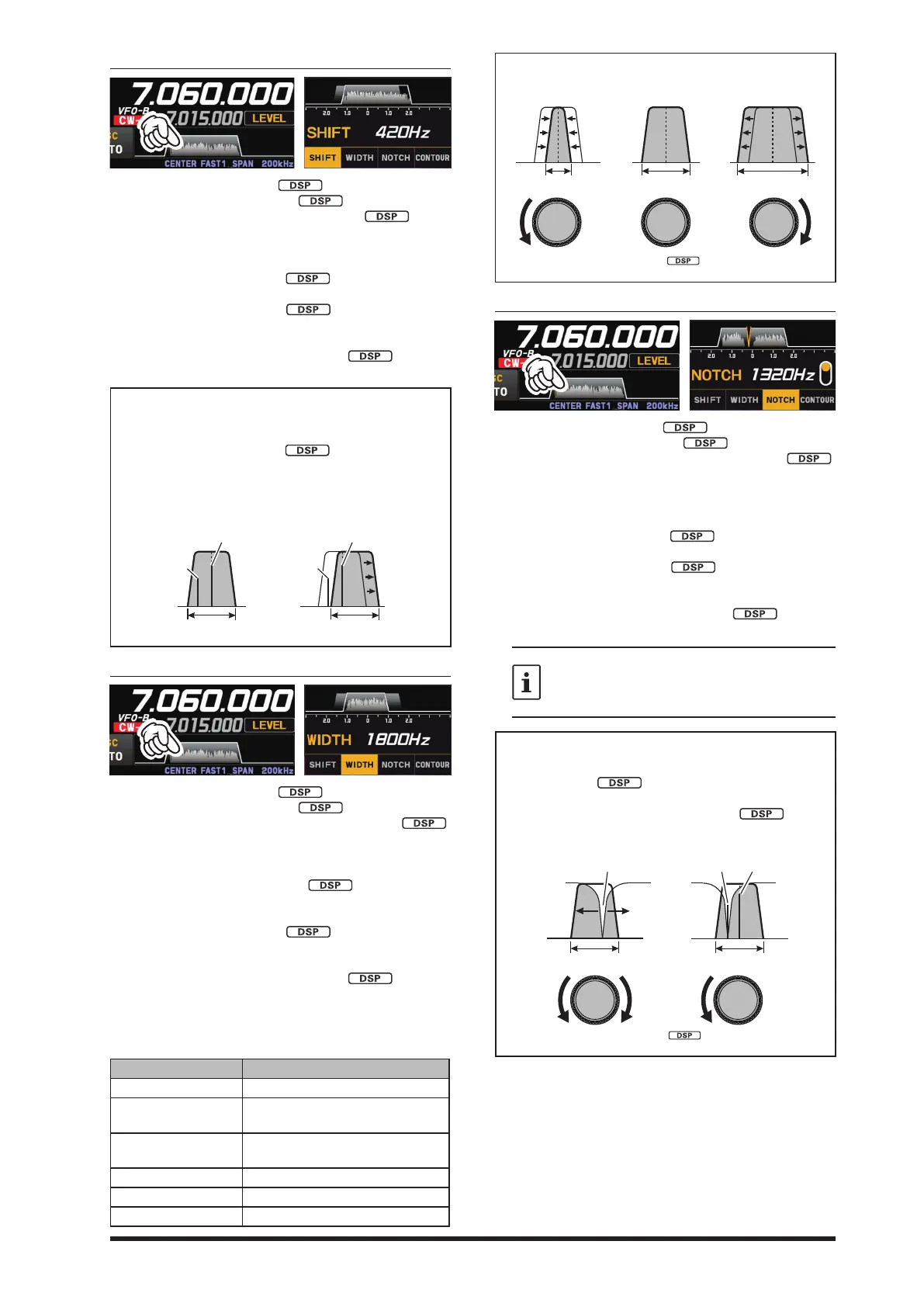
Refer to Figure “A” and notice the depiction of the
IF DSP filter as a thick line in the center of the
passband. In Figure “B", you can see the eect of
rotating the [STEP • MCH /
] knob.
The interference level is reduced by moving the l-
ter passband so that the interference is outside of
the passband.
A B
IF BANDWIDTH IF BANDWIDTH
Desired Signal
QRM
Desired Signal
2. WIDTH
1. Press the [STEP • MCH / ] knob.
2. Rotate the [STEP •MCH/
] knob to select
“WIDTH”, then press the [STEP •MCH /
]
knob. (The function may also be selected by touch-
ing “WIDTH”.)
The lter bandwidth blinks.
3. Rotate the [STEP •MCH /
] knob count-
er-clockwise to narrow the bandwidth and reduce
interference.
4. Press the [STEP •MCH /
] knob, then press
the [DSP RESET] key or wait for about 5 seconds to
save the setting.
Press and hold the [STEP • MCH /
] knob to
reset the digital lter bandwidth to its initial value.
The default bandwidths, and total bandwidth adjust-
ment range, will vary according to the operating mode
(see table below).
Operating Mode IF BANDWIDTH
LSB / USB 300Hz - 4000Hz (default: 3000Hz)
CW-L / CW-U
RTTY-L / RTTY-U
50Hz - 4000Hz (default: 500Hz)
DATA-L / DATA-U
PSK
50Hz - 4000Hz (default: 600Hz)
AM / FM-N / D-FM-N 9000Hz
AM-N 6000Hz
FM / DATA-FM 16000Hz
The figure below is a conceptual diagram of
WIDTH.
IF BANDWIDTH
•
3. NOTCH
1. Press the [STEP • MCH / ] knob.
2. Rotate the [STEP •MCH/
] knob to select
“NOTCH”, then press the [STEP •MCH /
]
knob.
(The function may also be selected by touching
“NOTCH”.)
The NOTCH center frequency blinks.
3. Rotate the [STEP • MCH /
] knob to adjust the
“null” position of the Notch lter.
4. Press the [STEP •MCH /
] knob, then press
the [DSP RESET] key or wait for about 5 seconds to
save the setting.
Press and hold the [STEP • MCH /
] knob to
return the center frequency to its initial value.
The bandwidth of the NOTCH filter (either
narrow or wide) may be adjusted using Menu
item “IF NOTCH WIDTH” (page 92).
The factory default setting is “WIDE”.
The performance of the IF Notch filter is shown
in Figure “A", where the effect of rotation of the
[STEP • MCH /
] knob is depicted. In Figure
“B” you can see the notching eect of the IF Notch
lter as you rotate the [STEP • MCH /
] knob
to eliminate the incoming interference.
Notch QRM (Heterodyne)
IF BANDWIDTH IF BANDWIDTH
•
 Loading...