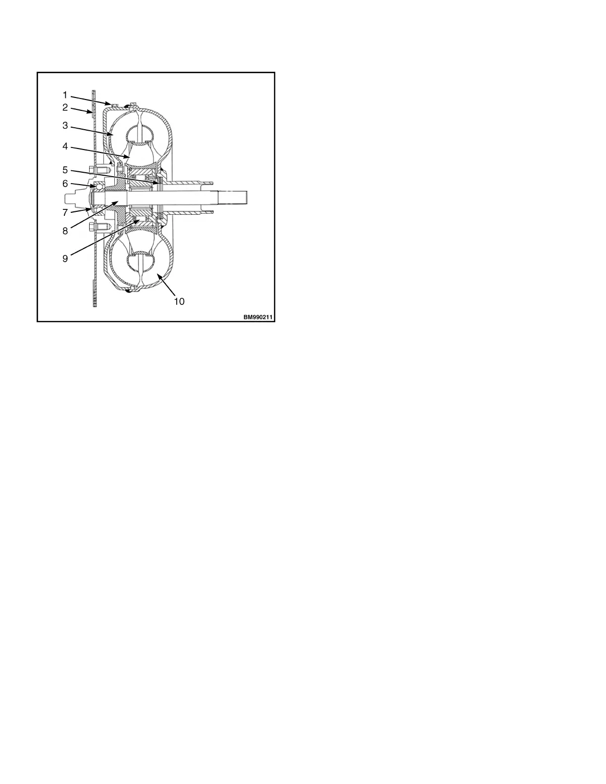
1. OIL DRAIN PLUG
2. FLEX PLATE
3. TURBINE
4. GUIDE PULLEY
5. THRUST BEARING
6. BALL BEARING
7. RETAINER RING
8. TURBO SHAFT
9. ONE-WAY CLUTCH
10. PUMP IMPELLER
Figure 8. Torque Converter
HYDRAULIC CLUTCH
Wet multi-disk hydraulic clutch is mounted on the input
shaft of hydraulic transmission case. It distributes oil
pressure to the forward or reverse clutch through the
control valve, this causes the forward and reverse gear
shift. All the gears in transmission case are normally-
engaged gears. Each clutch is composed of alternately
assembled, four spacers (item 18, Figure 9), four
brake shoes (item 19, Figure 9), and one piston (item
2, Figure 9). The internal and external surfaces of the
piston are fitted with seal rings to ensure a proper seal.
In NEUTRAL position, the piston does not interact with
the spacer and the brake shoe. While in gear, oil
pressure controls the piston. The spacer compresses
against the brake shoe, and an the adapter transmits
power from torque converter to the driving gears
(items 4 and 6, Figure 9).
The transmission of power from torque converter to
hydraulic transmission case is as follows:
Turbine → Input Shaft Assembly → Spacer →
Brake Shoe → Forward Gear or Reversing Gear →
Output Shaft
Hydraulic Transmission Case and Torque Converter 8000 YRM 2199
12
 Loading...