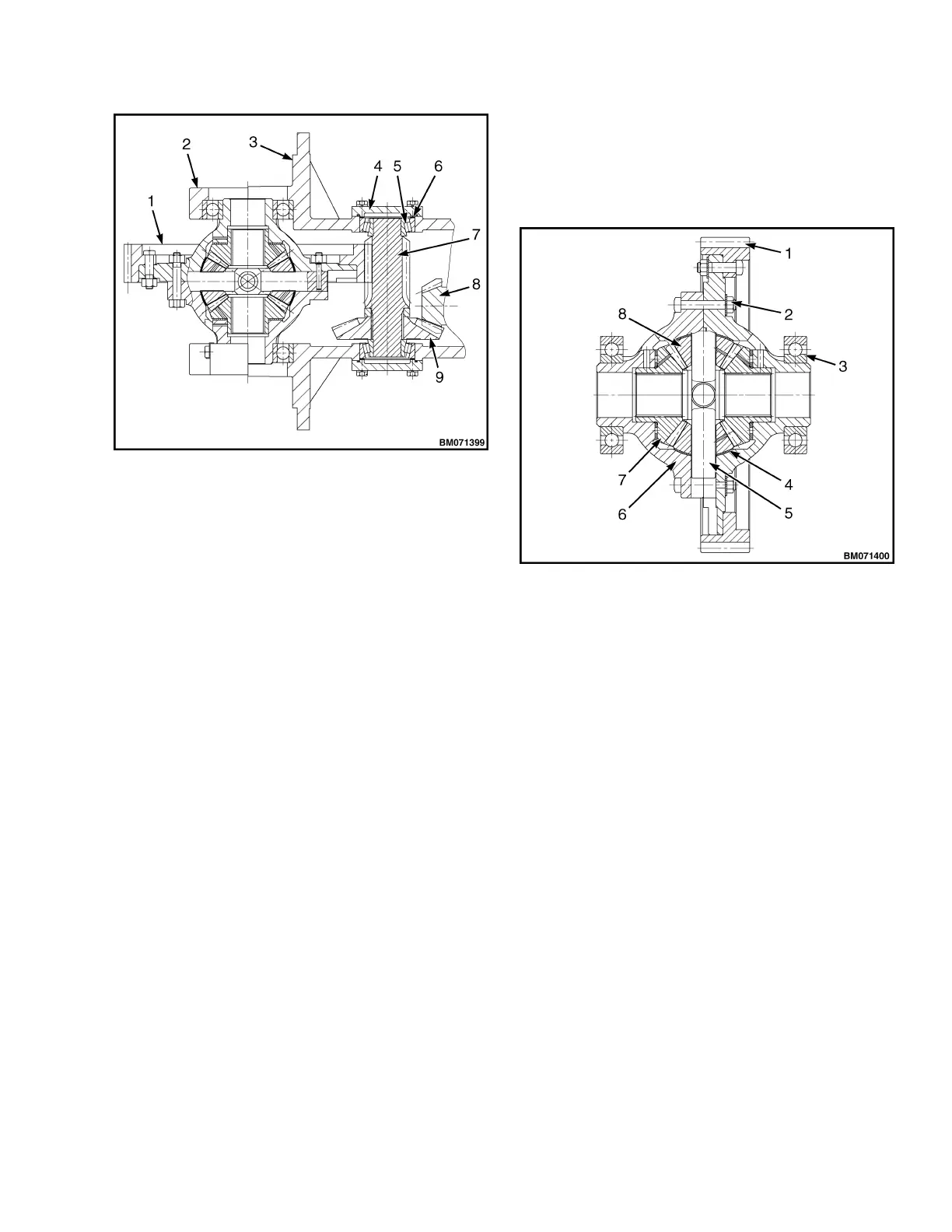
1. SPEED REDUCER ASSEMBLY
2. BEARING SEAT
3. SHELL
4. BEARING COVER
5. BEARING
6. GASKET
7. TERMINAL BEVEL GEAR SHAFT
8. DRIVING SPIRAL BEVEL GEAR
9. RING SPIRAL BEVEL GEAR
Figure 14. Speed Reducer
Speed Differential
The speed differential is mounted on the front of the
shell by a bearing seat and ball bearings on the two
ends. The front is connected to the axle shell. The
shell of speed differential is made into a type of left
and right parts, with two half shaft gears and four
planetary gears. The thrust washer is mounted
between the shell of speed differential and gear and it
is allowable for a clearance to be retained between
respective gear pairs. The planetary gears are
supported using gear shafts I and II, while gear shaft I
is fastened onto the body of speed differential using
cylindrical pink, and gear ring I is fixed onto the shell of
speed differential using articulated bolts. See
Figure 15.
A half shaft gear and half transmit power from the
transmission through the differential and to the wheels.
1. GEAR RING
2. BOLT
3. BEARING
4. COPPER PAD
5. CROSS AXLE
6. SPEED DIFFERENTIAL SHELL
7. HALF-AXLE GEAR
8. PLANETARY GEAR
Figure 15. Speed Differential
TOWING THE LIFT TRUCK
When the forklift truck with hydraulic transmission is
damaged and must be towed by other vehicles.
•
Remove the half shaft from the front wheel.
•
Place the gear-shift lever in the NEUTRAL
position.
8000 YRM 2199 Hydraulic Transmission Case and Torque Converter
17
 Loading...