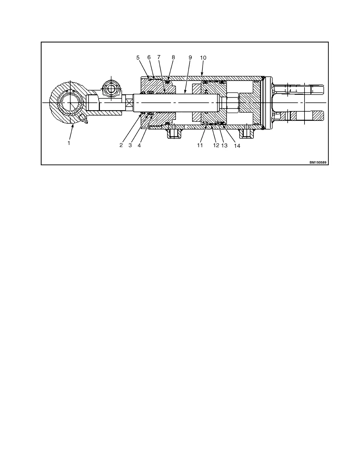
1. CLEVIS
2. DUST RING
3. BAFFLE RING
4. SEAL RING
5. O-RING
6. GUIDE SLEEVE
7. BEARING
8. O-RING
9. PISTON ROD
10. CYLINDER BODY
11. SEAL RING
12. WEAR RING
13. PISTON
14. SEAL RING
Figure 48. Tilting Cylinder
When tilt spool valve is pushed forward, the high-
pressure fluid enters from the bottom of the cylinder,
pushing the the piston forward and allowing the mast
to mast to tilt forward by 6°. When spool valve is pulled
backwards, the fluid enters from the front end of
cylinder body, to push the piston until the mast tips
backwards by 12°.
MAINTENANCE OF HYDRAULIC PUMP
Disassemble, Main Oil Pump
NOTE: For the following procedures refer to Figure 55
and Figure 56.
1. Clamp the pump gently on a vice stand after
cleaning. Remove the bolts (item 12).
2. Detach pump cover (item 1) and seal rings (items,
8, 9, 10, and 11).
3. Remove the front-end cover (item 7) and seal
rings.
4. Remove bearings and gears (items 3-6) from
pump body. Bearings may be removed by
pressing the gears, if it is difficult to remove them.
Inspection and Repair
Clean disassembled metal parts with hydraulic fluid.
Inspect, repair, or replace according to following
procedure.
Inspection of Pump Body
1. The gear pump is designed so the gear rotates
along the inner surface of the pump body. Under
normal wear its wear area shall not exceed a
length 1/3 of the inner edge of the pump body. If it
reads ½ length, it indicates that the bearing and
gear shaft are worn out. When size at "X"
exceeds 39.180 mm (1.542 in.), replace the pump
body. See Figure 49.
8000 YRM 2199 Hydraulic System
51
 Loading...