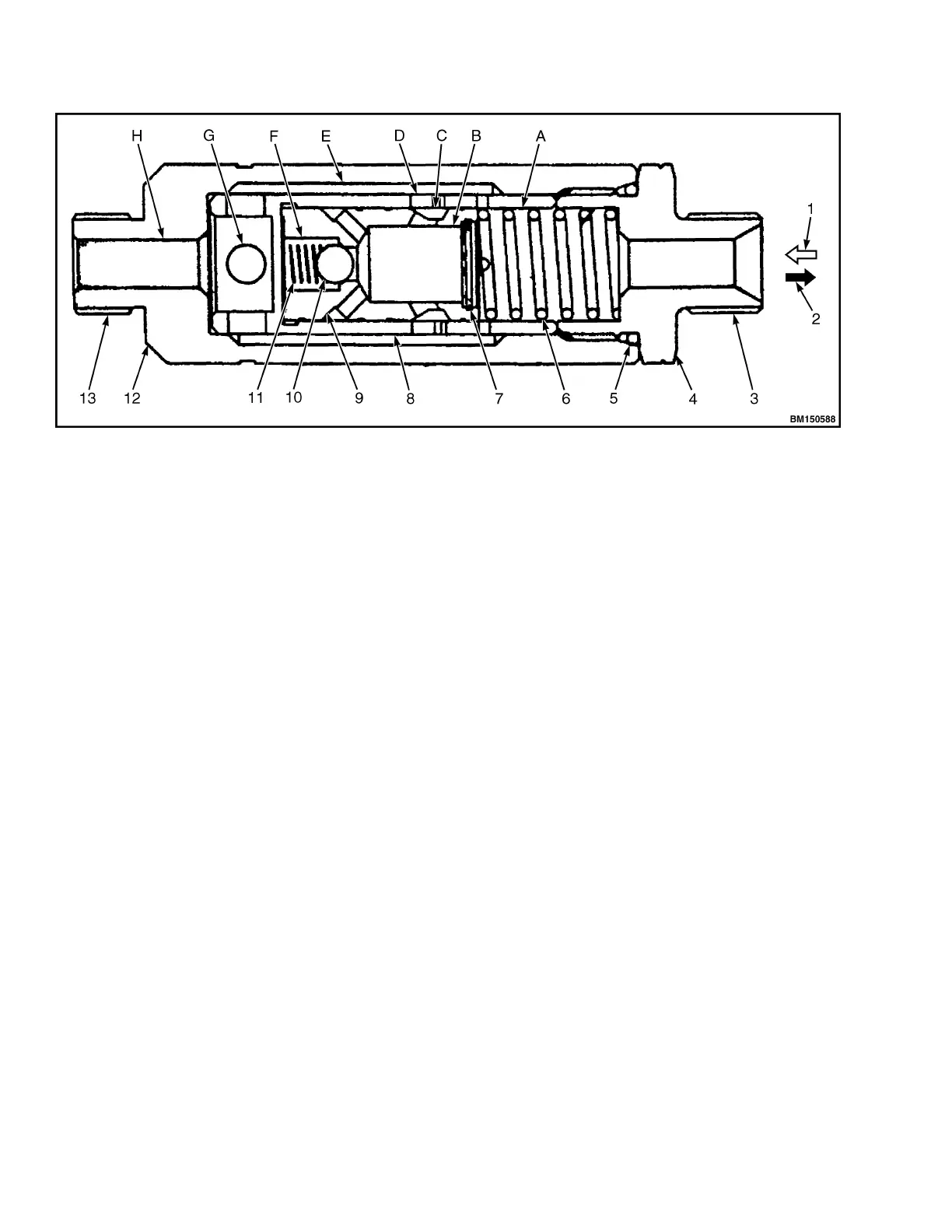
1. NORMAL FLOW
2. THROTTLE FLOW
3. SIDE OF MULTI-WAY VALVE
4. VALVE BODY
5. O-RING
6. SPRING
7. THROTTLE PLATE
8. VALVE SLEEVE
9. VALVE CORE
10. NYLON BALL
11. SPRING
12. CONNECTOR
13. SIDE OF LIFT CYLINDER
A. VALVE CAVITY
B. VALVE CAVITY
C. VALVE HOLE
D. VALVE HOLE
E. VALVE CAVITY
F. VALVE CAVITY
G. VALVE CAVITY
H. VALVE CAVITY
Figure 47. Limiting Valve
TILT CYLINDER
The tilt cylinder is a double acting cylinder, mounted on
each side of the mast.
The tilt cylinder assembly consist of the piston, piston
rod, cylinder body, cylinder bottom, guide sleeve, and
sealing parts. The piston and piston rods are welded
together. One wear ring and two Yx seal rings are
mounted on the outer edge of piston. A Yx seal ring
and dust rings are pressed in the cylinder bore and
matched with guide sleeve. The shaft sleeve supports
the piston rod, while the seal ring, and dust rings
prevent oil leaks and dust.
Hydraulic System 8000 YRM 2199
50
 Loading...