20 Troubleshooting
YASKAWA TOEPC7106171FD FP605 DRIVE INSTALLATION & PRIMARY OPERATION 119
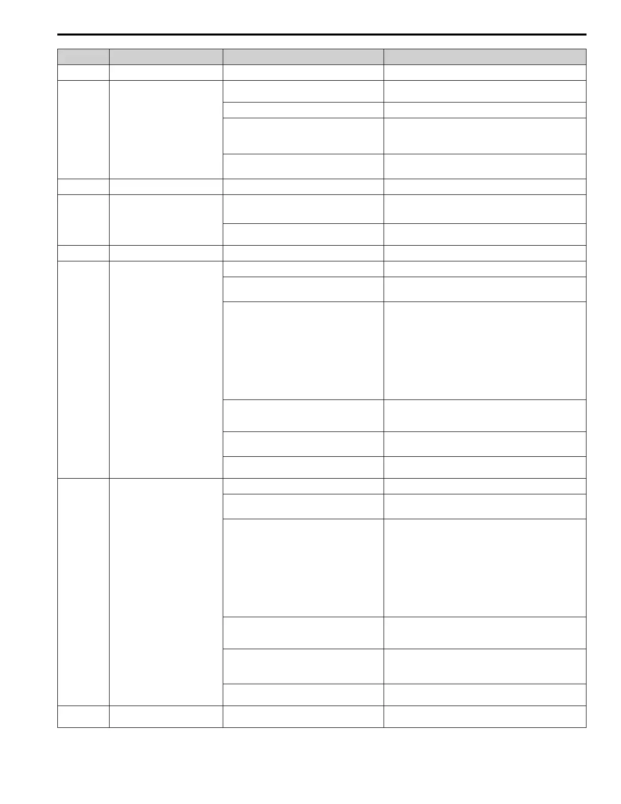
Code Name Causes Possible Solutions
Main PID Feedback Transducer is broken. Replace Main PID Feedback Transducer.
BuFbl Backup Fdbk Lost Chk/Repl Xducer
The drive detected wire-break on the analog input
terminal set for PID Feedback Backup [H3-xx = 24].
Examine the connection of the Differential PID Feedback
transducer.
Backup PID Feedback Transducer is broken. Replace Backup PID Feedback Transducer.
Parameter Y4-41 = 1 [Diff Lvl Src Fdbk Backup
Select = Enabled] and the drive detected a wire-break
on the analog input terminal set for Differential Level
Source [H3-xx = 2D].
Examine the connection of the Differential PID Feedback
transducer.
Parameter Y4-41 = 1 and the Differential PID
Feedback Transducer is broken.
• Replace the Differential PID Feedback Transducer.
• Set Y4-41 = 0 [Disabled].
bUS Option Communication Error
The communications cable wiring is incorrect. Correct wiring errors.
bUSy Busy
You set the drive to use MEMOBUS/Modbus
communications to change parameters, but you used
the keypad to change parameters.
Use MEMOBUS/Modbus communications to enter the enter
command, then use the keypad to change the parameter.
You tried to change a parameter while the drive was
changing setting.
Wait until the process is complete.
CALL Serial Comm Transmission Error
The communications cable wiring is incorrect. Correct wiring errors.
CE Modbus Communication Error
The communications cable wiring is incorrect. Correct wiring errors.
There is a short circuit in the communications cable
or the communications cable is not connected.
• Repair short circuits and connect cables.
• Replace the defective communications cable.
Electrical interference caused a communication data
error.
• Examine the control circuit lines, main circuit lines, and ground
wiring, and decrease the effects of electrical interference.
• Make sure that a magnetic contactor is not the source of the
electrical interference, then use a Surge Protective Device if
necessary.
• Use only the recommended cables or other shielded line. Ground
the shield on the controller side or the drive input power side.
• Separate the communication wiring from drive power lines, and
install a noise filter to the input side of the power supply for
communication.
• Decrease the effects of electrical interference from the controller.
The communication protocol is not compatible. • Examine the values set in H5-xx.
• Examine the settings on the controller side and correct the
difference in communication conditions.
The value set in H5-09 [CE Detection Time] is too
small for the communications cycle.
• Change the controller software settings.
• Increase the value set in H5-09.
The controller software or hardware is causing a
communication problem.
Examine the controller and remove the cause of the problem.
CE Run at H5-34 (CE Go-To-Freq)
The communications cable wiring is incorrect. Correct wiring errors.
There is a short circuit in the communications cable
or the communications cable is not connected.
• Repair short circuits and connect cables.
• Replace the defective communications cable.
Electrical interference caused a communication data
error.
• Examine the control circuit lines, main circuit lines, and ground
wiring, and decrease the effects of electrical interference.
• Make sure that a magnetic contactor is not the source of the
electrical interference, then use a Surge Protective Device if
necessary.
• Use only recommended shielded line. Ground the shield on the
controller side or on the drive input power side.
• Separate the communication wiring from drive power lines, and
install a noise filter to the input side of the power supply for
communication.
• Decrease the effects of electrical interference from the controller.
The communication protocol is not compatible. • Examine the values set in H5-xx.
• Examine the settings on the controller side and correct the
difference in communication conditions.
The value set in H5-09 [CE Detection Time] is too
small for the communications cycle.
• Make sure that the settings are compatible.
• Change the software settings in the PLC.
• Increase the value set in H5-09.
The controller software or hardware is causing a
communication problem.
Examine the controller and remove the cause of the problem.
CrST Cannot Reset
The drive received a fault reset command when a Run
command was active.
Turn off the Run command then de-energize and re-energize the
drive.
 Loading...