7 Electrical Installation
32 YASKAWA TOEPC7106171FD FP605 DRIVE INSTALLATION & PRIMARY OPERATION
Wire Gauge and Torque Specifications for UL Listing
WARNING
Electrical Shock Hazard. Make sure that the protective ground wire complies with technical standards and local
safety regulations. The IEC/EN 61800-5-1:2007 standard specifies that you must wire the power supply to automatically de-
energize when the protective ground wire disconnects. You can also connect a protective ground wire that has a minimum cross-
sectional area of 10mm
2
(copper wire) or 16 mm
2
(aluminum wire). For drive models on which you cannot use a protective ground
wire of 10 mm
2
or more, install two protective ground wires that have the same cross-sectional area. If you do not obey the
standards and regulations, it can cause serious injury or death. The leakage current of the drive will be more than 3.5 mA.
Refer to Three-Phase 208 V Class Wire Gauges and Torques on page 32 and Three-Phase 480 V Class Wire Gauges
and Torques on page 35 for the recommended wire gauges and tightening torques of the main circuit terminals.
Note:
The recommended wire gauges are based on drive continuous current ratings with 75 °C (167 °F) 600 V class copper wire. Assume these
conditions:
• Ambient temperature: 40 °C (104 °F) or lower
• Wiring distance: 100 m (3281 ft) or shorter
• Normal Duty Rated current value
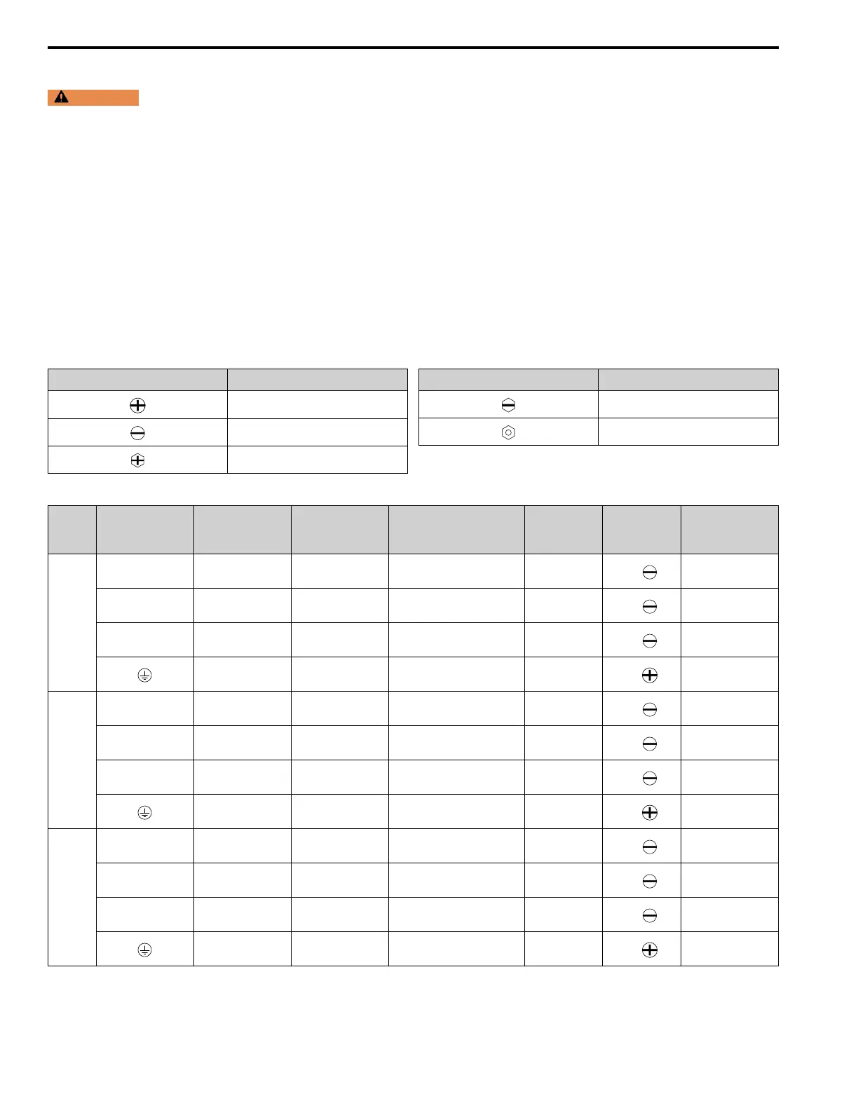
Screw Shapes
Table 7.2 Icons to Identify Screw Shapes
Icon Screw Shape
Phillips/slot combo (+/-)
Slotted (-)
Hex bolt (cross-slotted)
Icon Screw Shape
Hex bolt (slotted)
Hex self-locking nut
Three-Phase 208 V Class Wire Gauges and Torques
Model Terminals
Recommended
Gauge
AWG, kcmil
Applicable Gauge
AWG, kcmil
(mm
2
)
*1
IP20 Applicable Gauge
*2
AWG, kcmil
(mm
2
)
*1
Wire Stripping
Length
*3
mm
Terminal Screw
Size and Shape
Tightening Torque
N∙m (lbf∙in)
2011
R/L1, S/L2, T/L3 14
14 - 8
(2.5 - 10)
- 10
M4
1.5 - 1.7
(13.5 - 15)
U/T1, V/T2, W/T3 14
14 - 8
(2.5 - 10)
- 10
M4
1.5 - 1.7
(13.5 - 15)
-, +1 14
14 - 8
(2.5 - 10)
- 10
M4
1.5 - 1.7
(13.5 - 15)
12
14 - 8
(2.5 - 10)
- -
M5
2.0 - 2.5
(17.7 - 22.1)
2017
R/L1, S/L2, T/L3 12
14 - 8
(2.5 - 10)
- 10
M4
1.5 - 1.7
(13.5 - 15)
U/T1, V/T2, W/T3 10
14 - 8
(2.5 - 10)
- 10
M4
1.5 - 1.7
(13.5 - 15)
-, +1 10
14 - 8
(2.5 - 10)
- 10
M4
1.5 - 1.7
(13.5 - 15)
10
14 - 8
(2.5 - 10)
- -
M5
2.0 - 2.5
(17.7 - 22.1)
2024
R/L1, S/L2, T/L3 10
14 - 8
(2.5 - 10)
- 10
M4
1.5 - 1.7
(13.5 - 15)
U/T1, V/T2, W/T3 8
14 - 8
(2.5 - 10)
- 10
M4
1.5 - 1.7
(13.5 - 15)
-, +1 8
14 - 8
(2.5 - 10)
- 10
M4
1.5 - 1.7
(13.5 - 15)
10
14 - 8
(2.5 - 10)
- -
M5
2.0 - 2.5
(17.7 - 22.1)
 Loading...