5 Peripheral Devices
5.3.3 Terminal Descriptions
5-10
(2) Model: HV-75AP4/UL
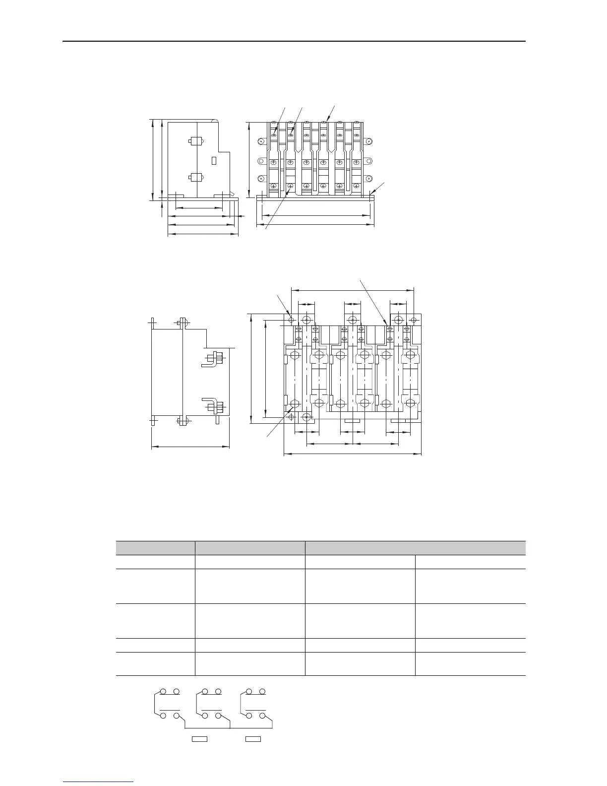
(3) Model: HV-150AP4, HV-150AP4/UL
5.3.3 Terminal Descriptions
The terminal name and operation status are shown below. For mounting direction, refer to 5.3.4 Installation
Orientation.
123456
7
8
9
10
11
12
13
14
15 16
17
18
145
160
107
97
105
85
65
1102.5
112.5
Main circuit terminals (M5)
Control circuit terminals (M4)
4-M6 mounting holes
Unit: mm
3434
1
7
2
8
3
9
4
5
11
6
12
22
170
22
22
168
148
192
34 343434 343434
64 64
108
10
Control circuit terminals (M4)
4-M6 mounting holes
Main circuit
terminals (M8)
Unit: mm
Ter mi na l Name Operation Status
13–14 Selection signal +24 V (Low-speed winding) 0 V (High-speed winding)
1–2
3–4
5–6
Main contact: 3NC Open Closed
7–8
9–10
11–12
Main contact: 3NO Closed Open
15–16 Auxiliary contact: 1NC Open Closed
17–18
Single-phase
200 V power supply
––
12
78
34
910
56
11 12
HV- AP4㧘HV-ޓޓAP4/UL
 Loading...


