EasyManuals Logo
Home>YASKAWA>Servo Drives>UAK series

YASKAWA UAK series User Manual

YASKAWA UAK series
340 pages
To Next Page IconTo Next Page
To Previous Page IconTo Previous Page
Page #144 background imageLoading...
Page #144 background image
7.2 Σ-V-SD Driver
7-19
Wiring
7
7.2 Σ -V-SD Driver
7.2.1 Main Circuit
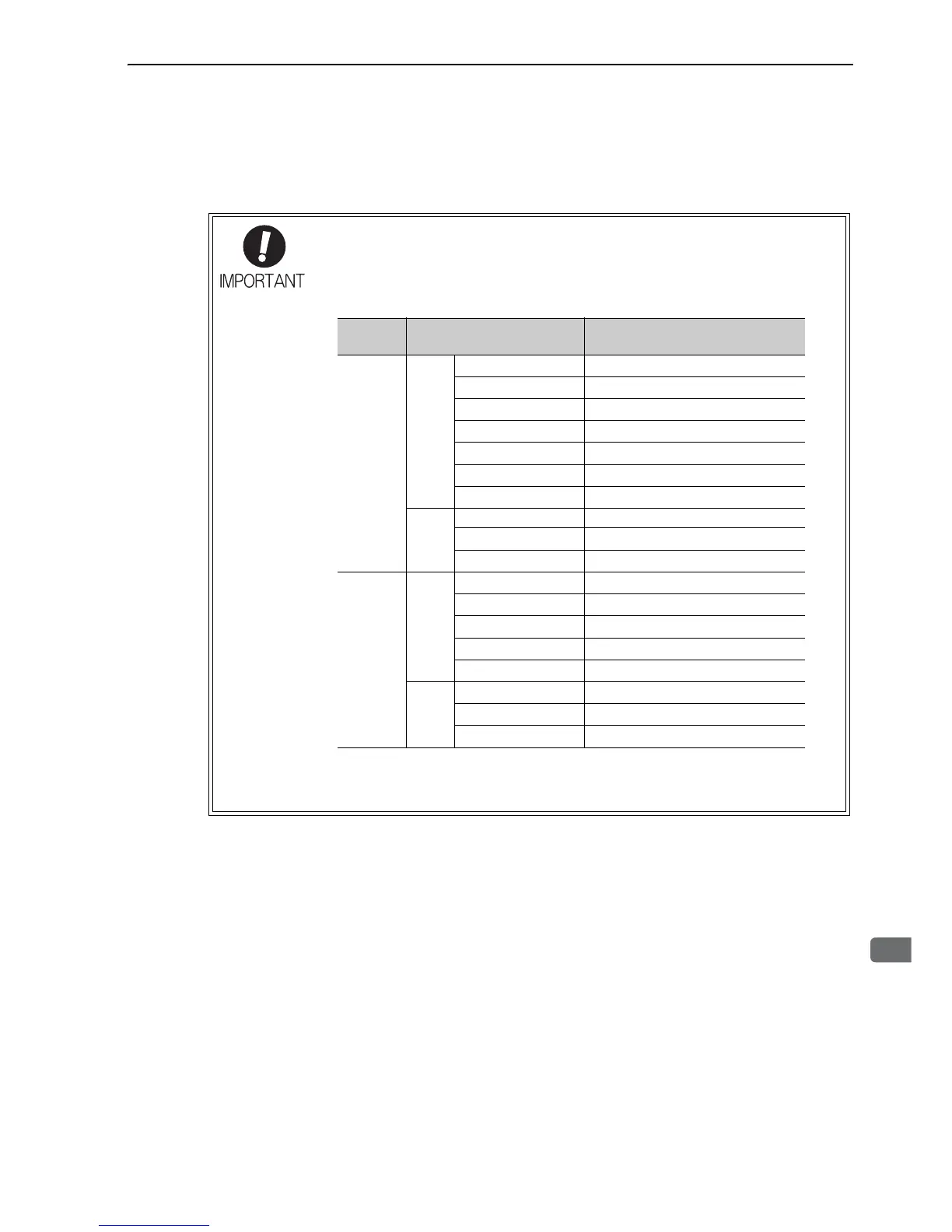
• Do not touch the power terminals before the main-circuit capacitor has had time to dis-
charge because high voltage may still remain in the converter and SERVOPACK. Refer
to the following table for the discharge time of main-circuit capacitor.
• When two or more SERVOPACKs are used in combination, use the longest discharge
time of those SERVOPACKs for the main-circuit capacitor.
First make sure the charge indicator is turned OFF and that the DC-bus (symbol: P and
N) voltage value is correct by using a tester or other device before wiring or starting an
inspection.
Input
Voltage
SERVOPACK Model
Discharge Time Needed for
Main-Circuit Capacitor (min)
Three-
phase,
200 VAC
For
one
axis
CACR-JU028ACA 15
CACR-JU036ACA 20
CACR-JU065ACA 20
CACR-JU084ACA 20
CACR-JU102ACA 25
CACR-JU125ACA 25
CACR-JU196ACA 25
For
two
axes
CACR-JUM23ACA 15
CACR-JUM24ACA 15
CACR-JUM25ACA 15
Three-
phase,
400 VAC
For
one
axis
CACR-JU014DCA 10
CACR-JU018DCA 15
CACR-JU033DCA 15
CACR-JU042DCA 15
CACR-JU051DCA 15
For
two
axes
CACR-JUM23DCA 15
CACR-JUM24DCA 15
CACR-JUM25DCA 15

Table of Contents

Questions and Answers:

Question and Answer IconNeed help?

Do you have a question about the YASKAWA UAK series and is the answer not in the manual?

YASKAWA UAK series Specifications

General IconGeneral
BrandYASKAWA
ModelUAK series
CategoryServo Drives
LanguageEnglish

Related product manuals