<APPENDIX 8. PID BLOCK>
A8-2
IM 01F06F00-01EN
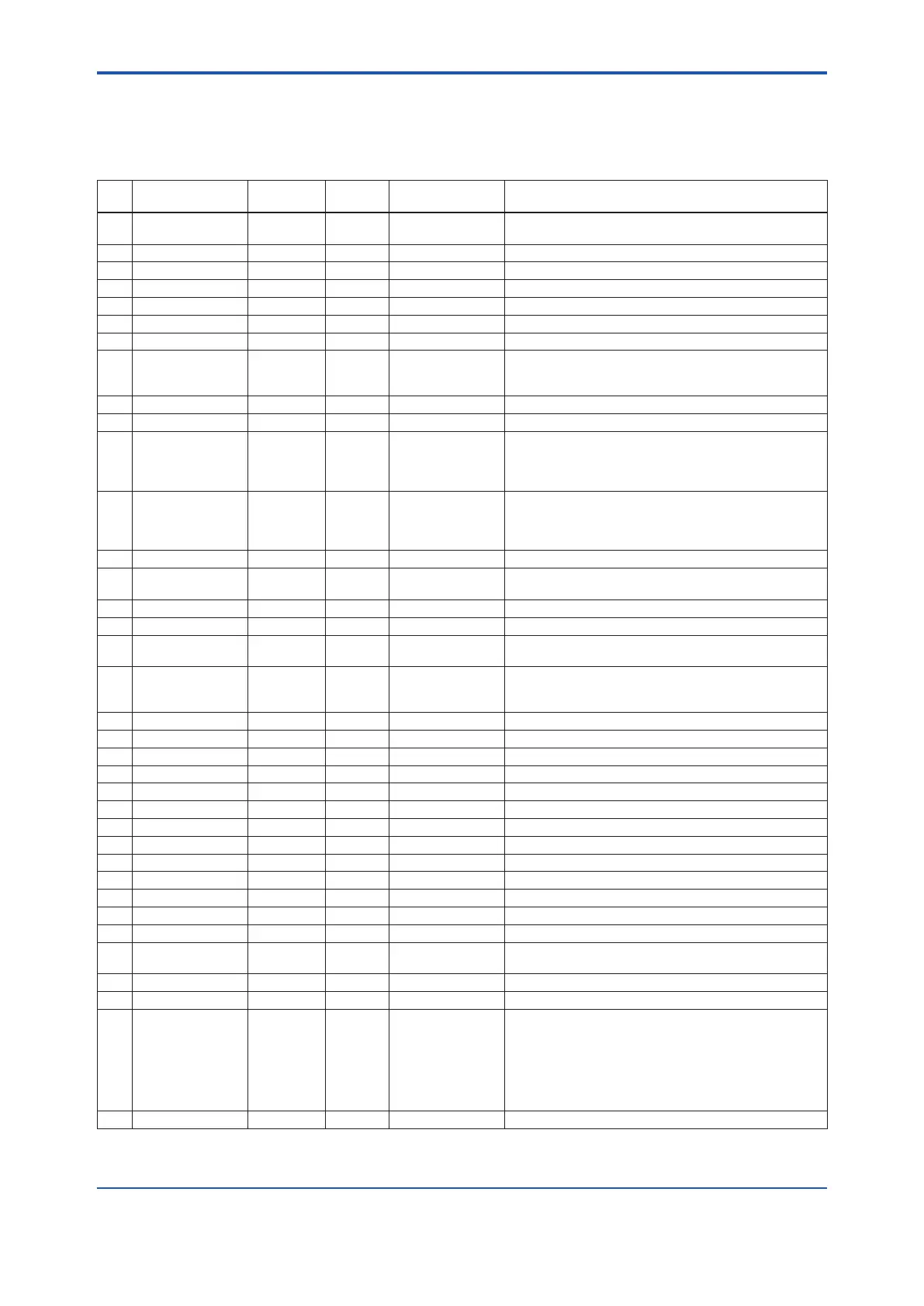
A8.3 Parameters of PID Block
NOTE: In the table below, the Write column shows the modes in which the respective parameters can be
written. A blank in the Write column indicates that the corresponding parameter can be written in all modes of
the PID block. A dash (–) indicates that the corresponding parameter cannot be written in any mode.
Index
Parameter Name
Default
(factory setting)
Write Valid Range Description
0 Block Header TAG: “PID” Block Tag
= O/S
Same as that for an AI block.
1 ST_REV – Same as that for an AI block.
2 TAG_DESC (blank) Same as that for an AI block.
3 STRATEGY 0 Same as that for an AI block.
4 ALERT_KEY 1 1 to 255 Same as that for an AI block.
5 MODE_BLK
6 BLOCK_ERR – Same as that for an AI block.
7 PV – Measured value; the non-dimensional value that is
converted from the input (IN) value based on the PV_
SCALE values and ltered.
8 SP 0 AUTO PV_SCALE ±10% Setpoint
9 OUT MAN Output
10 PV_SCALE 100
0
1342 (%)
1
O/S Upper and lower scale limit values used for scaling of the
input (IN) value.
11 OUT_SCALE 100
0
1342 (%)
1
O/S Upper and lower scale limit values used for scaling of the
control output (OUT) value to the values in the engineering
unit.
12 GRANT_DENY 0 AUTO Same as that for an AI block.
13 CONTROL_OPTS 0 O/S Setting for control action. Read APPENDIX 8.13 “Measured-
value Tracking” for details.
14 STATUS_OPTS 0 O/S Read APPENDIX 8.15 “Manual Fallback” for details.
15 IN 0 Controlled-value input
16 PV_FTIME 0sec AUTO Non-negative Time constant (in seconds) of the rst-order lag lter applied
to IN
17 BYPASS 1 (off) MAN 1, 2 Whether to bypass the control computation.
1 (off): Do not bypass.
2 (on): Bypass.
18 CAS_IN 0 Cascade setpoint
19 SP_RATE_DN 1.#INF Positive Rate-of-decrease limit for setpoint (SP)
20 SP_RATE_UP 1.#INF Positive Rate-of-increase limit for setpoint (SP)
21 SP_HI_LIM 100 PV_SCALE ±10% Upper limit for setpoint (SP)
22 SP_LO_LIM 0 PV_SCALE ±10% Lower limit for setpoint (SP)
23 GAIN 1 Proportional gain (= 100 / proportional band)
24 RESET 10 Integration time (seconds)
25 BAL_TIME 0 Positive Unused
26 RATE 0 Positive Derivative time (seconds)
27 BKCAL_IN 0 Read-back of control output
28 OUT_HI_LIM 100 OUT_SCALE ±10% Upper limit for control output (OUT)
29 OUT_LO_LIM 0 OUT_SCALE ±10% Lower limit for control output (OUT)
30 BKCAL_HYS 0.5 (%) 0 to 50% Hysteresis for release from a limit for OUT.status
31 BKCAL_OUT 0 – Read-back value to be sent to the BKCAL_IN in the upper
block
32 RCAS_IN 0 Remote setpoint set from a computer, etc.
33 ROUT_IN 0 Remote control output value set from a computer, etc.
34 SHED_OPT 0 Action to be performed in the event of mode shedding.
SHED_OPT denes the changes to be made to MODE.
BLK.target and MODE.BLK.actual when the value of
RCAS_IN.status or ROUT_IN.status becomes Bad if
MODE_BLK.actual = RCas or ROut.
Read APPENDIX 8.17 “Mode Shedding upon Computer
Failure.”
35 RCAS_OUT 0 – Remote setpoint sent to a computer, etc.

 Loading...


