<APPENDIX 8. PID BLOCK>
A8-10
IM 01F06F00-01EN
A8.19
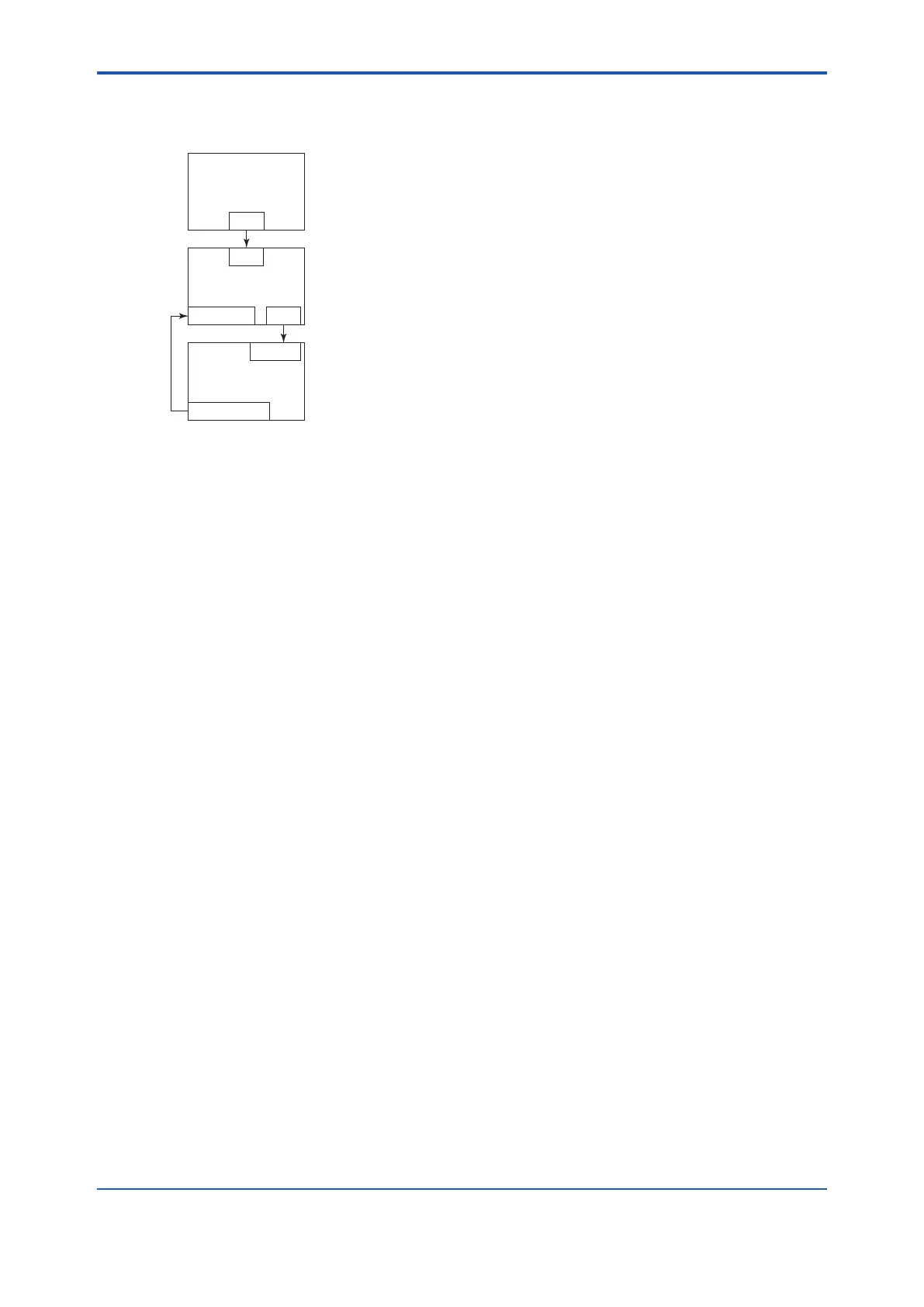
Example of Block
Connections
PID
BKCAL_IN OUT
IN
AO
BKCAL_OUT
CAS_IN
AI
OUT
FA0808.ai
When conguring a simple PID control loop by
combining a digitalYEWFLO with a eldbus valve
positioner that contains an AO block, follow the
procedure below to make the settings of the
corresponding eldbus function blocks:
1. Connect the AI block and PID block of the
digitalYEWFLO, and the AO block of the valve
positioner as shown above.
2. Set MODE_BLK.target of the PID block to
O/S, and then set GAIN, RESET, and RATE to
appropriate values.
3. Check that the value of MODE_BLK.actual of
the AI block is AUTO.
4. Set MODE_BLK.target of the AO block to
CAS|AUTO (meaning “CAS and AUTO”).
5. Check that the value of BKCAL_IN.status of the
PID block is not Bad.
6. Check that the value of IN.status of the PID
block is not Bad.
7. Check that AUTO is set in MODE_BLK.
permitted of the PID block.
8. Set MODE_BLK.target of the PID block to
AUTO.
When nishing all steps in order, the PID block and
AO block exchange the respective information and
initialize the cascade connection. Consequently,
the value of MODE_BLK.actual of the PID block
changes to AUTO and automatic PID control starts.

 Loading...


