<10. COMMISSIONING OF ISC (Inductive Conductivity)>
10-6
IM 12A01A02-01E 8th Edition : Oct. 01, 2015-00
l Unit for table
Select the concentration display units from among %, ppt, ppm, and ppb. Changing the unit will
not result in a re-calculation of the table. Reenter values in the additional concentration table.
10.1.7 Sensor diagnostic settings
This screen is used to set items relating to sensor diagnostics displayed on the screens invoked
by pressing
.
Gauges are displayed for only parameters that have been enabled in “Sensor diag. settings.”
Parameters set to Disable are provided with a bar display.
The setting parameters include Progress time and Heat cycle. It is also possible to set the “Bad
limits” of the progress time and heat cycle and the “Heat cycle temp” and “Heat cycle time” of the
heat cycle.
10.2 Output setup
The general procedure is to rst dene the function of the output, Output or Simulate. Then, set
the process parameters associated with the output. On the Output, an output of measured value
is selected. On the Simulate, a simulation value can be set.
And, the parameters for HOLD function can be set on this setting.
l Output
The output signal is a current value specied by the following parameters.
Process parameter
Available process parameters depend on the selected “Measurement” item in Measurement
setup. Refer to Table 10.2.
The output of the selected process parameter is shown as a bar on the bottom of the Main
display. And its parameter symbol (for example, Conduct1-TC1) is shown above the bar, too.
When a selected process parameter is displayed as a measurement value, the top left number
or character is turned to be white number or character on black background (for example,
).
(Refer to the section 1.2.)
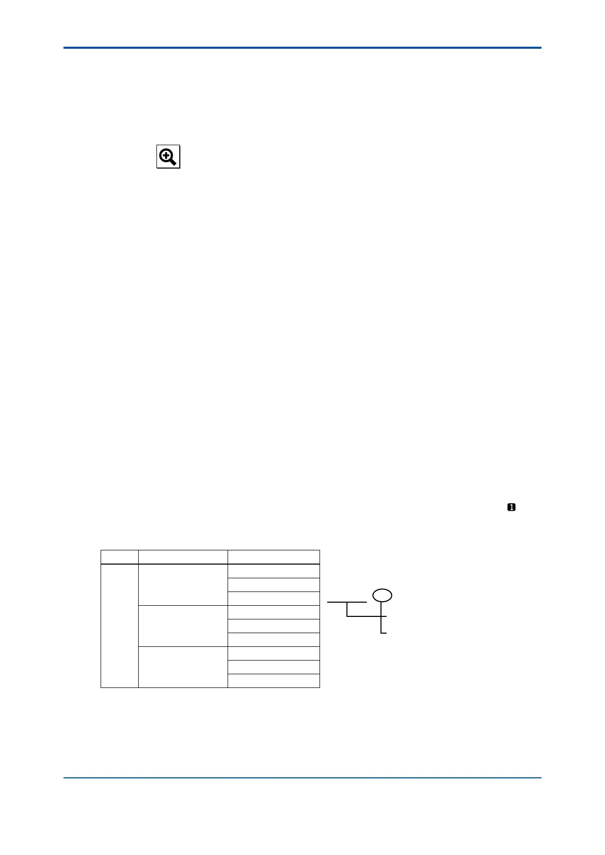
Table 10.2 List of Process Parameters
Sensor Measurement Process Parameters
1
Conductiivity
Conduct1-TC1
Conduct1 - TC1 :
Conductivity of sensor 1
Temperature compensation 1
Select the temperature compensation
method is section 10.1.4.
Temperature1
Conduct1-TC2
Concentration
Conduct1-TC1
Temperature1
Concent1-TC2
Conduct. + Concentr.
Conduct1-TC1
Temperature1
Concent1-TC2
Setup
Select one of the output methods: Linear and Table.
Linear: Set the 0% and 100% values.
Table: This allows the conguration of an output curve by 21 points (5% intervals).
(The 0% and 100% values must be entered.)

 Loading...