<2. WIRING AND INSTALLATION>
2-18
IM 12A01A02-01E 8th Edition : Oct. 01, 2015-00
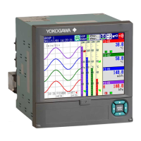
2.5.2 Wiring the conductivity (SC) sensor
Contacting Conductivity, SC, sensors are connected to the module as follows:
11 +
-
V-
i-
Temp
V+
i+
12
13
14
15
16
FLXA202/FLXA21
The above diagram shows wiring for 4-electrode conductivity sensors, such as SC42-SP34
large bore series. For 2-electrode conductivity sensors, such as SC42-SP36 small bore series,
jumpers must be installed between terminals 13-14 and between terminals 15-16, as shown in
the diagram below.
11 +
-
V-
i-
Temp
V+
i+
12
13
14
15
16
FLXA202/FLXA21
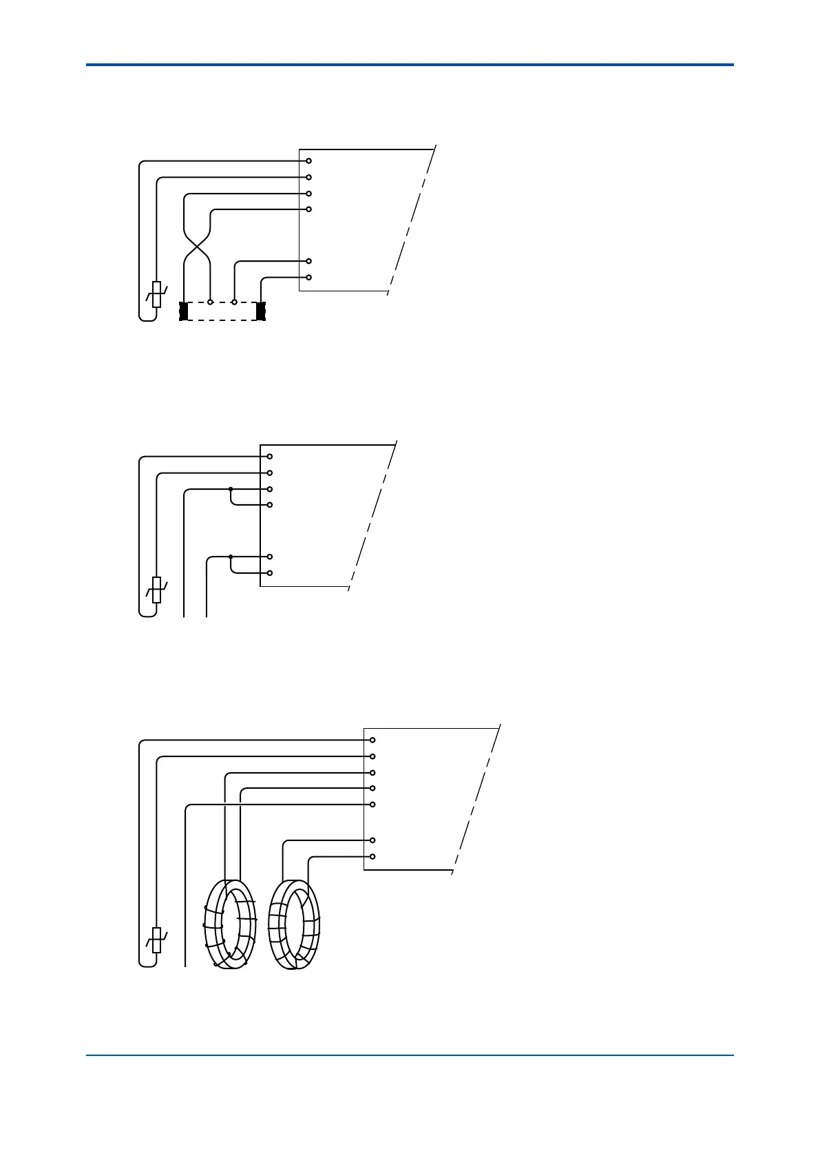
2.5.3 Wiring the inductive conductivity (ISC) sensor
ISC40 sensors are connected to the module as follows:
11 +
-
Temp
Receive coil
Drive coil
12
13
17
15
16
14
shield
Sensor shield
(internal)
shield
FLXA202/FLXA21
The sensors are supplied with integral cables and each individual wire is marked with the
corresponding terminal numbers.

 Loading...