<1. INTRODUCTION AND GENERAL DESCRIPTION>
1-17
IM 12A01A02-01E 8th Edition : Oct. 01, 2015-00
Electrical Parameters (Nonincendive)
Housing Assembly
Supply and output circuit (terminals + and -)
Ui(Vmax)=30V, Ci=13nF, Li=0mH
Measuring module input circuit (CN2 or CN3 on Back board)
Uo(Vt,Voc)=13.65V, Io(It,Isc)=50mA, Co(Ca)=80nF, Lo(La)=7.7mH
pH module, SC module and DO module
Ui(Vmax)=13.92V, Ci=40nF, Li=2.9mH
Sensor input circuit (terminals 11 through 19)
Uo(Vt,Voc)=11.76V, Io(It,Isc)=116.5mA, Co(Ca)=4uF, Lo(La)=4.5mH
ISC module
Ui(Vmax)=13.92V, Ci=40nF, Li=7.7mH
Sensor input circuit (terminals 11 through 17)
Uo(Vt,Voc)=11.76V, Io(It,Isc)=60.6mA, Co(Ca)=4uF, Lo(La)=19mH
Note for Intrinsically Safe Installation:
1: In any safety barrier used, the output current must be limited by a resistor “R” such that Io=Uo/R or Isc=Voc/R.
2: The safety barrier must be CSA certied.
3: Input voltage of the safety barrier must be less than 250Vrms/Vdc
4: When using non isolation barrier connect (*1) to IS earthing system.
5: pH and SC Sensor(s) are of a passive type to be regarded as ‘simple apparatus’ same as 06ATEX0218X, 06ATEX0219,
IECEx KEM 06.0052X, FM3028779, 06ATEX0220X, 06ATEX0221, IECEx KEM 06.0053X or the one individually certied with
relevant parameters.
6: ISC Sensor(s) are ISC40S of 00ATEX1067X or the one individually certied with relevant parameters.
7: DO Sensor(s) are of a passive type to be regarded as ‘simple apparatus’ or the one individually certied with relevant
parameters.
8: Measuring module 2 may not mounted. As for ISC module, only one can be mounted.
9: Installation should be in accordance with Canadian Electrical Code Part I and Local Electrical Code.
10: Do not alter drawing without authorization from CSA.
Note for Nonincendive Installation:
1: The parameter for sensor input circuit must be taken into account when installed.
2: Installation should be in accordance with Canadian Electrical Code Part I and Local Electrical Code.
3: Do not alter drawing without authorization from CSA.
NEPSI
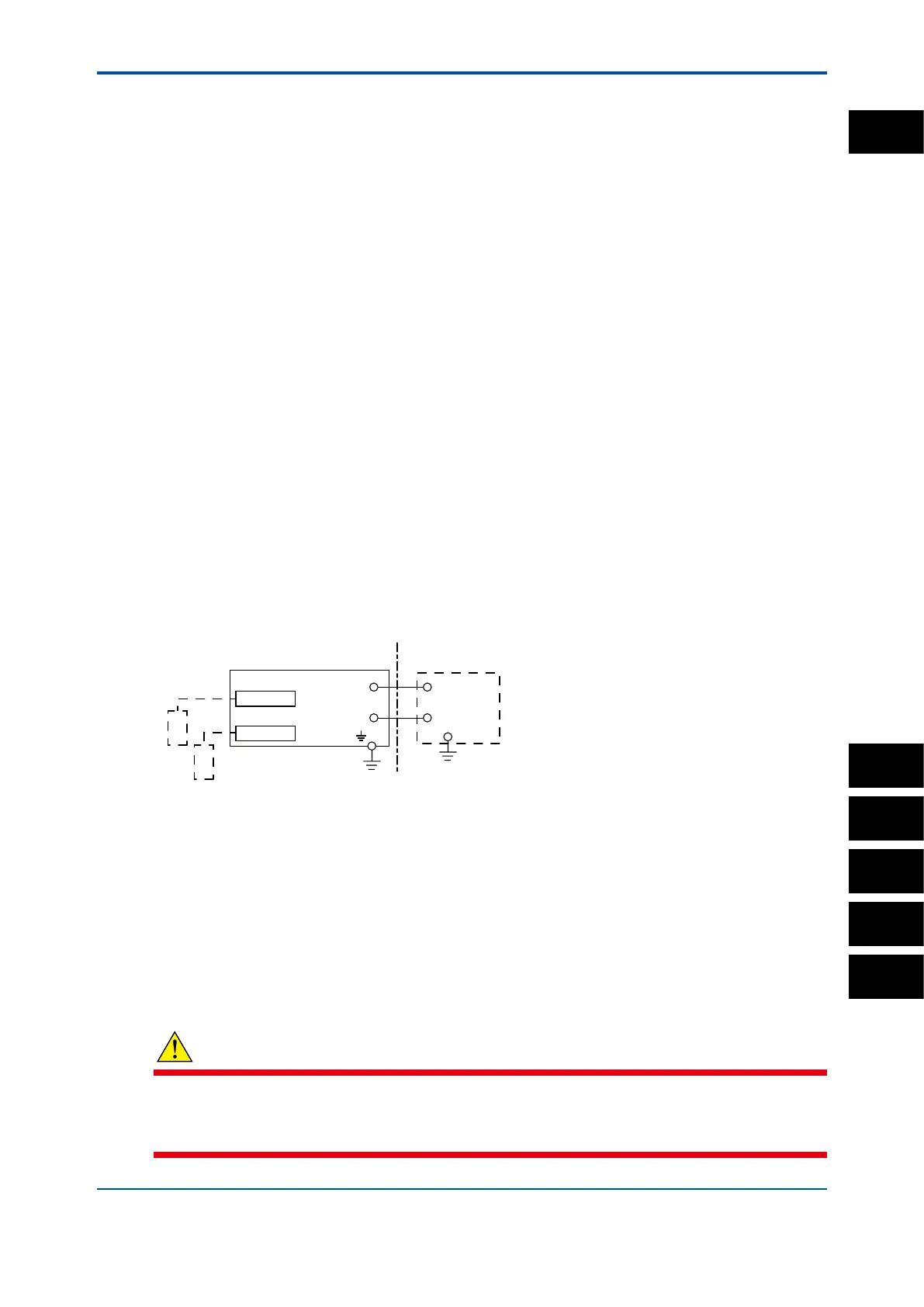
Control Drawing (for 4-20mA type)
Measuring module 1
Note: The measuring module on this drawing means
the sensor module on this General Specifications.
Measuring module
2
Sensor 1
Sensor 2
(*)
(Note 1)
Safety Barrier
Housing Assembly
Supply
-
Supply
+
→
Non Hazardous Location
Hazardous Location ←
-
+
Electrical data are as follows;
Maximum Voltage (Ui) = 30 V
Maximum Current (Ii) = 100 mA
Maximum Power (Pi) = 0.75 W
Internal Capacitance (Ci) = 13 nF
Internal Inductance (Li) = 0 mH
Note 1: The output current must be limited by a resistor “R” such that Imaxout=Uz/R (linear source).
Note 2: Safety barrier certied by NEPSI should be used.
Note 3: When using non isolation barrier, connect (*) to IS earthing system.
Note 4: Sensor module 2 is installed when required.
When measuring inductive conductivity, only one module can be installed.
WARNING
Installation and wiring
The FLXA202/FLXA21 should only be used with equipment that meets the relevant IEC,
American or Canadian standards. Yokogawa accepts no responsibility for the misuse of this unit.
1
PH
SC
ISC
DO
SENCOM

 Loading...