<11. CALIBRATION OF ISC (Inductive Conductivity)>
11-2
IM 12A01A02-01E 8th Edition : Oct. 01, 2015-00
NOTE
The standard instrument to be used in calibration with a process solution should always be
accurate. Yokogawa recommends that the Model SC72 pocket conductivity meter be used for
this purpose.
Where temperature compensation 1 (SC1) and temperature compensation 2 (SC2) have been
congured, the congured temperature compensation is effective even during calibration.
Therefore, the reading is the value converted to a conductivity value at the reference temperature
set in Temperature settings.
There are temperature compensation 1 (SC1) and temperature compensation 2 (SC2), but this
does not mean that calibration is required twice. It means that either SC1 or SC2 temperature
compensation should be selected and calibration should be made once to obtain the cell
constant. The cell constant after calibration can be checked on the Detail screen.
NOTE
When a sensor is exchanged or replaced, sensor wellness data should be reset.
When a sensor is replaced, the replacement can be recorded manually into a logbook. (Refer to
the gure 9.8.)
l Cell constant
The center value of the cell constant of the ISC40 sensor is 1.88 cm
-1
. The nominal cell constants
of individual sensors are indicated on the cable markers and the actual installation can change
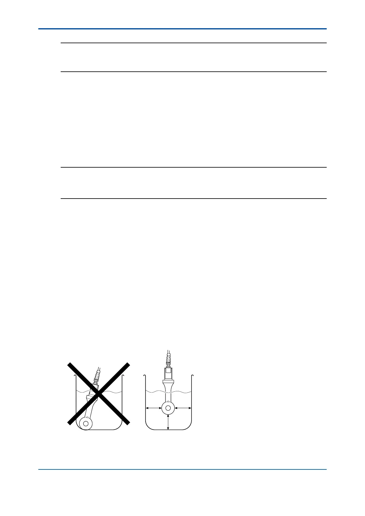
this factor. If there is less than 30 mm spacing between a sensor and holder, in-situ calibration is
necessary to meet the specied accuracies.
• If the sensor is installed in the stainless steel standard holder ISC40FFJ-S, the cell constant
is reduced by approximately 7%; enter a value 7% smaller than the value on the marker of
the sensor cable.
• If the sensor is installed in the polypropylene standard holder ISC40FFJ-P, the cell constant
is increased by approximately 1%; enter a value 1% greater than the value on the sensor
cable marker.
• If the sensor is installed in piping that is long in the axial direction with the cross section
as shown in Figure 11.3, the cell constant of the sensor installed in the piping (reference
data for a design center value of 1.88 cm
-1
) is as shown in Figure 11.3. A value obtained by
multiplying the value on the sensor cable marker and a value read from Figure 11.3 should
be entered.
X= 30 mm (Min.)
XX
X
Figure 11.2 Sensor in calibration solution

 Loading...