<2. WIRING AND INSTALLATION>
2-2
IM 12A01A02-01E 8th Edition : Oct. 01, 2015-00
(Plastic housing)
(Stainless steel
housing)
*2 *2
*4
*5
*6
*6
n n n n n n n n n
n n n n n n n n n
+
–
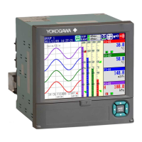
*1: Use a 2-wire shielded cable with an outside diameter of 6 to 12 mm.
*2: Connect the analyzer to ground. (Class D ground: 100 ohm or less)
The way of connecting the grounding cable varies depending on the plastic housing and stainless steel
housing.
In the case of the plastic housing, connect the grounding cable to the terminal of the power module inside,
and in the case of the stainless steel housing, connect the grounding cable to the terminal of the housing.
Use a cable with an outside diameter of 3.4 to 7 mm for the grounding line of the plastic housing.
The minimum cross sectional area of the protective grounding cable should be 0.75 mm
2
.
Although, on the stainless steel housing, the ground terminal symbol is (protective ground), the ground is
really functional ground.
*3: This line is connected to a distributor or 24V DC power supply.
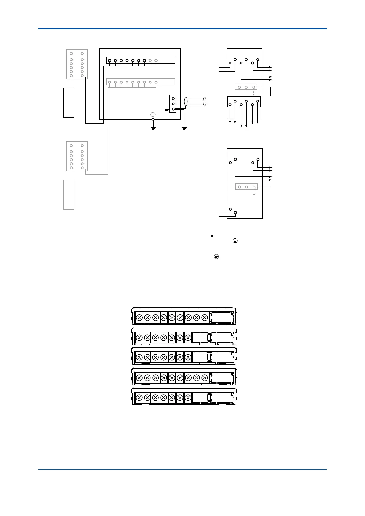
*4: Terminal numbers for each sensor module are shown below.
*5: Two modules of the same kind of measurement/sensor type can be installed. When measuring inductive
conductivity or pH/ORP with the SENCOM sensor, only one module can be installed.
*6: The terminal box may be necessary depending on the sensor cable length and the distance between the
analyzer and the sensor.
The SENCOM sensor is to be connected directly to the analyzer without a terminal box.
*7: Two outputs, output 1 and output2, of PH201G or SDBT are same signals.
*1
WTB10 or BA10
Terminal box
FLXA21 2-Wire Analyzer
Sensor
WTB10 or BA10
Terminal box
Sensor
PH Module
SC Module
ISC Module
DO Module
SENCOM Module
16
15191713181412
11
PH
NC
18171413151612
11
DO
151614171312
11
ISC
NC1615141312
11
SC
8786NC848382
NC
SENCOM
Power supply
Output 1 (1-5V DC)
20 to 130V DC
or
80 to 138V AC, 47 to 63Hz
Power supply
20 to 130V DC
or
80 to 138V AC, 47 to 63Hz
HOLD WASH
FAIL
Output 2 (1-5V DC)
Output 1 (1-5V DC)
Output 2 (1-5V DC)
Case of Distributor
PH201G (Style B)
Case of Distributor
SDBT
(*3)
*3
*7
*7
(*3)
A
+
–
CMN CMN
B
C
D
F
H
L N
A
+
–
+
–
B
1
+
–
2
F
H
L N
b
a
d
c
f
e
Figure 2.2 FLXA21 Wiring diagrams

 Loading...