<1. INTRODUCTION AND GENERAL DESCRIPTION>
1-2
IM 12A01A02-01E 8th Edition : Oct. 01, 2015-00
1
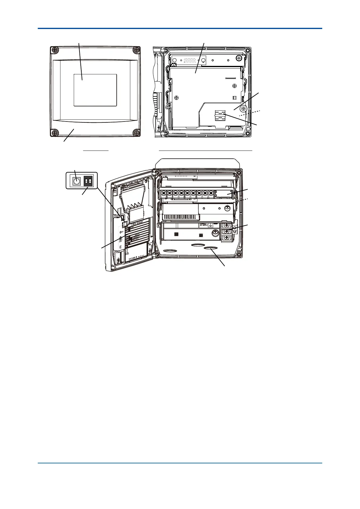
ON
2
ON
Cable entry holes
Wiring cover 1 (for the first module)
Jumper holder
(provided only for
pH measurement)
Front view
Front view with the front panel opened
Front view with all wiring covers removed
Reboot switch
(Do not use it)
Terminal block
for power supply
LCD display
Slide switch
(for HART only)
Wiring cover 2
(for the second module)
Front panel
The first module
(The second module if any
is installed here.)
Nameplate
(Wiring cover 3 for power
supply and grounding is
under the wiring cover 2.)
Figure 1.2 FLXA21 Parts names and descriptions

 Loading...