Page – 102/155 AF6ZP0CA – COMBIAC0 & ACE0 2uC – User Manual
The microcontroller constantly monitors the inverter and carries out a diagnostic
procedure on the main functions.
For simple visual diagnosis of system faults and to monitor system status, a red
LED is provided on the body of the controller.
Alarm LED
At start-up it is turned ON for 2 seconds and then it stays continuously OFF when
there is no fault.
In case of fault it produces flash codes displaying all the active faults in a
repeating cycle.
Each code consists of two digits (see chapter 10) shown through the following
sequence:
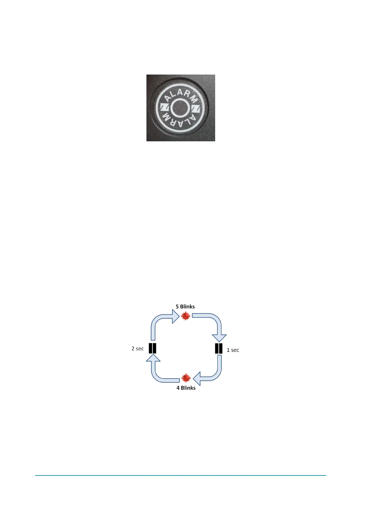
1) the LED blinks as much times as the first digit value
2) it makes a pause of 1 sec
3) it blinks as much times as the second digit value.
The sequence it is repeated after a pause of 2 sec
In case of fault concerning supervisor uC the sequence is the same with the only
difference that LED stays ON for 2 sec before to start for flashing the appropriate
code.
Examples:
- Alarm 54 on master uC
- Alarm 54 on supervisor uC
 Loading...