Page – 24/155 AF6ZP0CA – COMBIAC0 & ACE0 2uC – User Manual
4.4.3 Analog inputs
Analog inputs are for functions such as accelerator or brake references and they
are acquired through a 10-bits analog-to-digital converter (resolution is given by
the voltage excursion over 1024 levels).
Circuit
Input impedance and maximum frequency for analog inputs in standard Zapi
configurations are listed below. Custom hardware may feature different values.
Inverter voltage 24 V, 36/48 V 80 V
Input impedance
99 k 143 k
Maximum frequency
13 Hz 10 Hz
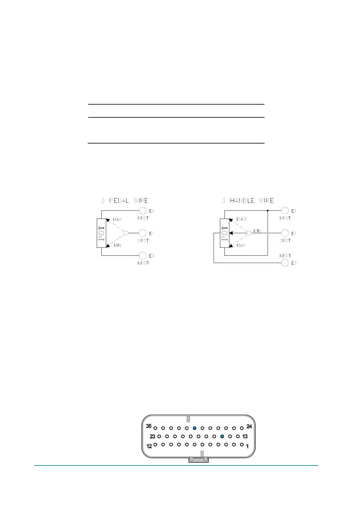
The standard connection for the potentiometer is that on the left side of next
figure: potentiometer at rest on one end, in combination with a couple of travel-
demand switches. On request it is also possible to have the configuration on the
right side of next figure: potentiometer at rest in the middle, still in combination
with a couple of travel-demand switches.
Potentiometer configuration
Negative supply of the potentiometer is to be taken from A5 (GND).
Potentiometer resistance should be in the 0.5 k – 10 k range; generally, the
load should be in the 1.5 mA to 30 mA range.
A procedure for automatic acquisition of potentiometers signals can be carried
out using the console (see paragraphs 9.1, 9.2 and 9.3).
Analog inputs may also be used as extra digital inputs. In such a case, the digital
input state is derived by SW from the ADC result. For example, a proximity switch
supplied from +B could be connected to an analog input.
Protection
Analog inputs are protected against short circuits to +B and -B. Each one has a
22 nF capacitor to -B for ESD protection.
Connector position
A15, A30.
 Loading...