AF6ZP0CA – COMBIAC0 & ACE0 2uC – User Manual Page – 93/155
Throttle signal
[% of MAX VACC]
Speed setpoint
[% of MAX VACC]
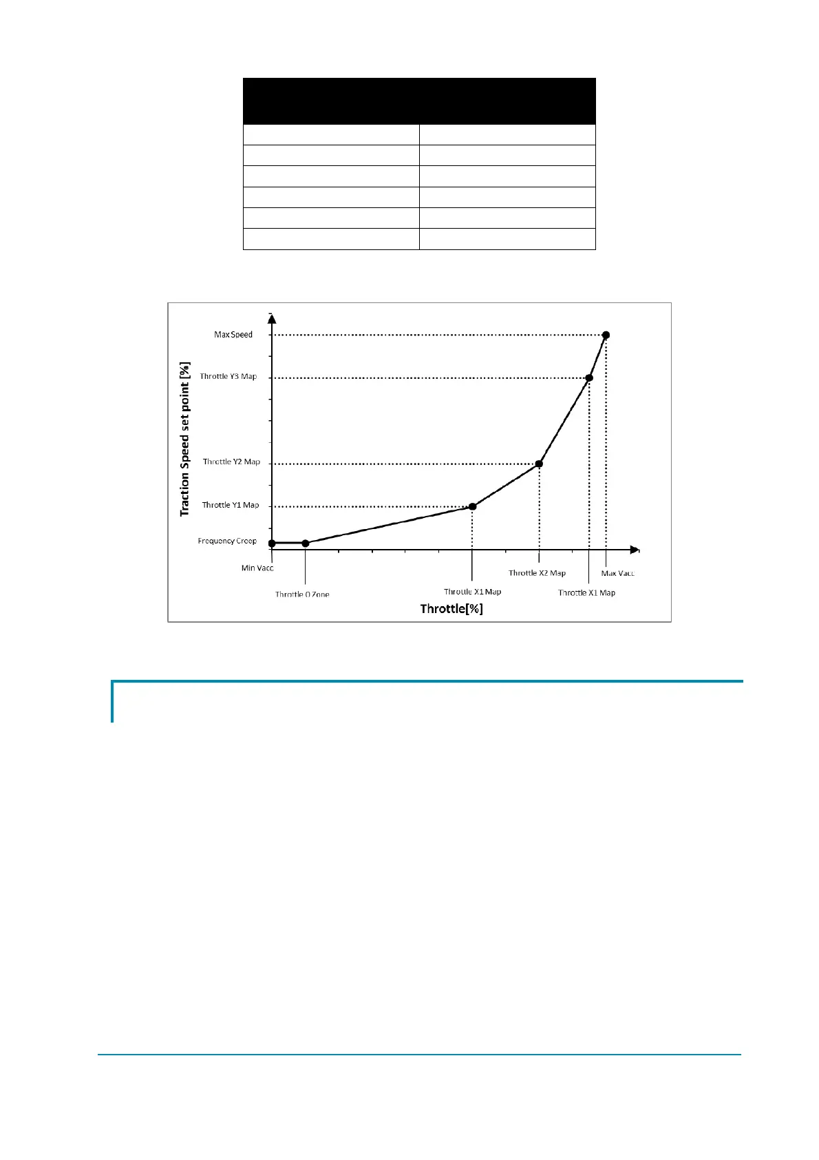
0 FREQUENCY CREEP
THROTTLE 0 ZONE FREQUENCY CREEP
THROTTLE X1 POINT THROTTLE Y1 POINT
THROTTLE X2 POINT THROTTLE Y2 POINT
THROTTLE X3 POINT THROTTLE Y3 POINT
MAX VACC MAX SPEED
The following graph better displays the throttle – speed relationship.
Throttle profile.
9.9 NMC & NEB output
For the NMC output [or NEB output] there is the possibility to set a pull-in voltage
and to define a retention voltage continuously applied to the coil.
MC VOLTAGE [or EB VOLTAGE] parameter specifies the duty cycle applied in
the first second after key-on and MC VOLT RED [or EB VOLT RED] determines
the duty-cycle applied after that, necessary to keep the contactor closed [or brake
disengaged] according to this formula:
%
∙
 Loading...