Page – 94/155 AF6ZP0CA – COMBIAC0 & ACE0 2uC – User Manual
NMC & NEB output management.
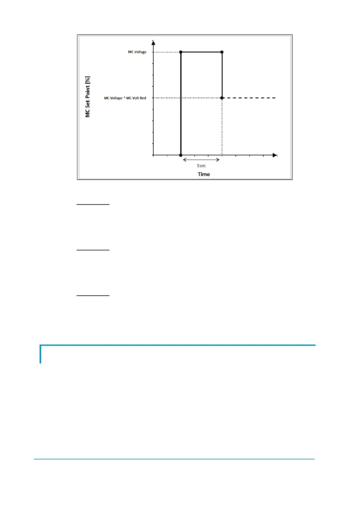
Example 1:
MC VOLTAGE = 100%
MC VOLTAGE RED = 70%
Contactor is closed by applying 100% of duty-cycle to the coil and then then it is
reduced to 70%.
Example 2:
MC VOLTAGE = 70%
MC VOLTAGE RED. = 100%
Contactor is closed by applying 70% of duty-cycle to the coil and then it is kept at
the same value.
Example 3:
MC VOLTAGE = 70%
MC VOLTAGE RED = 70%
Contactor is closed by applying 70% of duty-cycle to the coil and then it is
reduced to 49% (70% of 70%).
9.10 Battery-charge detection
During operating condition, the battery-charge detection makes use of two
parameters that specify the full-charge voltage (100%) and the discharged-
battery voltage (10%): BAT.MAX.ADJ and BAT.MIN.ADJ.
It is possible to adapt the battery-charge detection to your specific battery by
changing the above two settings (e.g. if the battery-discharge detection occurs
when the battery is not totally discharged, it is necessary to reduce
BAT.MIN.ADJ).
Moreover, BDI ADJ STARTUP adjusts the level of the battery charge table at the
start-up, in order to evaluate the battery charge at key-on. The minimum variation
of the battery charge that can be detected depends on the BDI RESET
 Loading...