Page – 18/155 AF6ZP0CA – COMBIAC0 & ACE0 2uC – User Manual
4 I/O INTERFACE DESCRIPTION
4.1 Power connectors
Power connections are on vertical posts where to bolt power-cables lugs. On the
cover of the converter they are labeled as:
Terminal name Description
+B Positive battery termination
-B Negative battery termination
U, V, W Motor phase terminations.
-P Negative terminal of pump DC motor (COMBIAC0 only).
In combination with COMBIAC0, DC pump motor must be connected between
terminals +B and -P. PWM frequency at -P is 16 kHz. Terminal -P is protected by
short circuit detection, voltage and current measurements. Freewheeling diodes
to +B are built in (MOSFETs internal diodes).
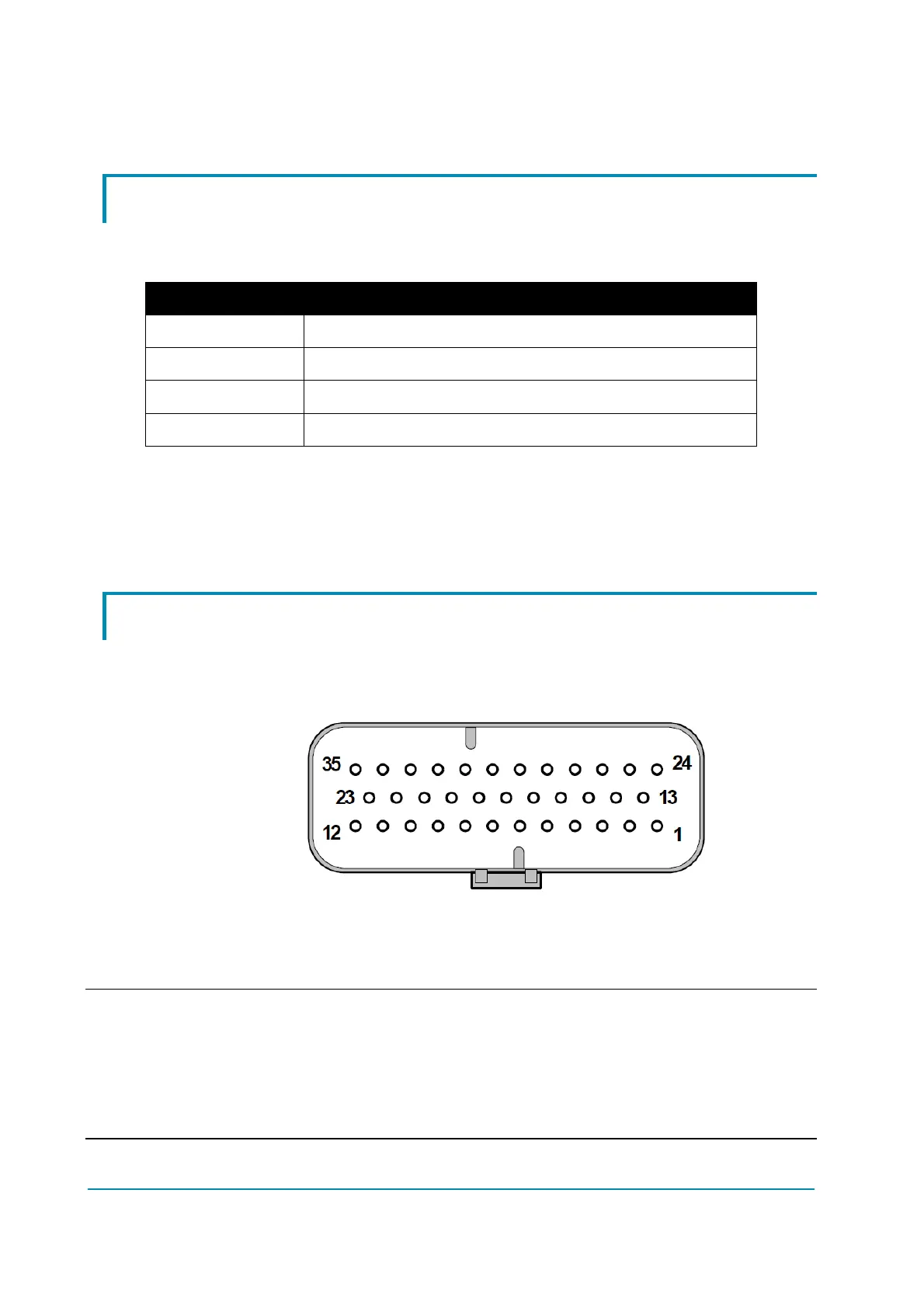
4.2 Ampseal connector
Inverter is equipped with a 35-poles Ampseal connector like that of the figure.
Each of the 35 pins is referred to as “A#”, where “A” denotes the connector name
and “#” the pin number, from 1 to 35.
35-poles Ampseal connector.
The following table lists the functional associations for the pins of the 35-poles
Ampseal connector.
4 For each I/O pin, the default Zapi function is indicated. The function of each pin
can be changed in customized software.
4 Some I/O pins can have special functionalities depending on the controller
configuration.
 Loading...