Page – 92/155 AF6ZP0CA – COMBIAC0 & ACE0 2uC – User Manual
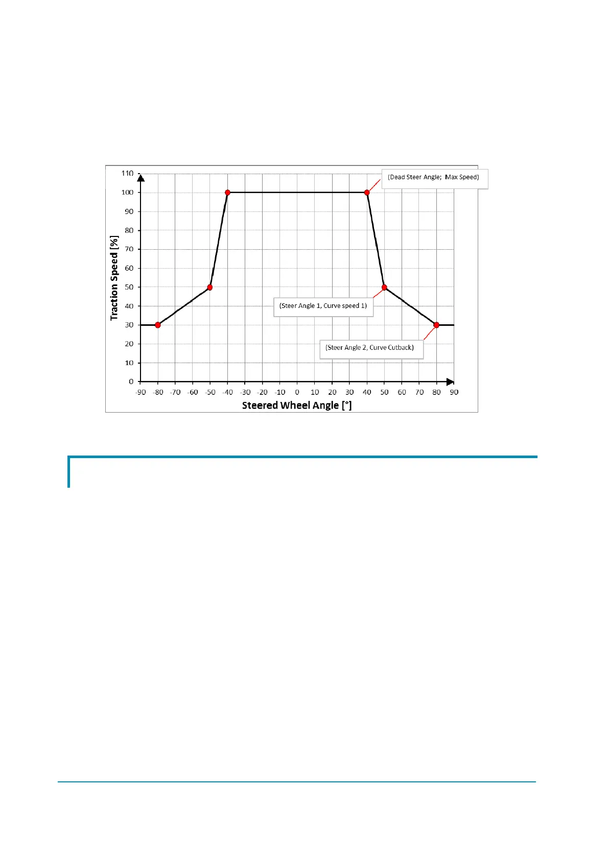
CURVE SPEED 1 = 50%
CURVE CUTBACK = 30%
STEER DEAD ANGLE = 40°
STEER ANGLE 1 = 50°
STEER ANGLE 2 = 80°
This set of parameters define the speed profile depicted in the graph below.
Steering curve.
9.8 Description of the throttle regulation
ACE0/CombiAC0 controls the truck speed by means of a not linear function of
the accelerator position, as to provide a better resolution of the speed control
when the truck is moving slowly.
For the definition of such response, the following parameters are used:
THROTTLE 0 ZONE [% of MAX VACC]
THROTTLE X1 POINT [% of MAX VACC]
THROTTLE Y1 POINT [% of MAX SPEED]
THROTTLE X2 POINT [% of MAX VACC]
THROTTLE Y2 POINT [% of MAX SPEED]
THROTTLE X3 POINT [% of MAX VACC]
THROTTLE Y3 POINT [% of MAX SPEED]
The speed remains at the FREQUENCY CREEP value as long as the voltage
from the accelerator potentiometer is below THROTTLE 0 ZONE. Basically this
defines a dead zone close to the neutral position.
For higher potentiometer voltages, the speed setpoint grows up as a polygonal
chain defined by the following table of points.
 Loading...