Page – 130/139 AFFZP0BB – ACE3 – User Manual
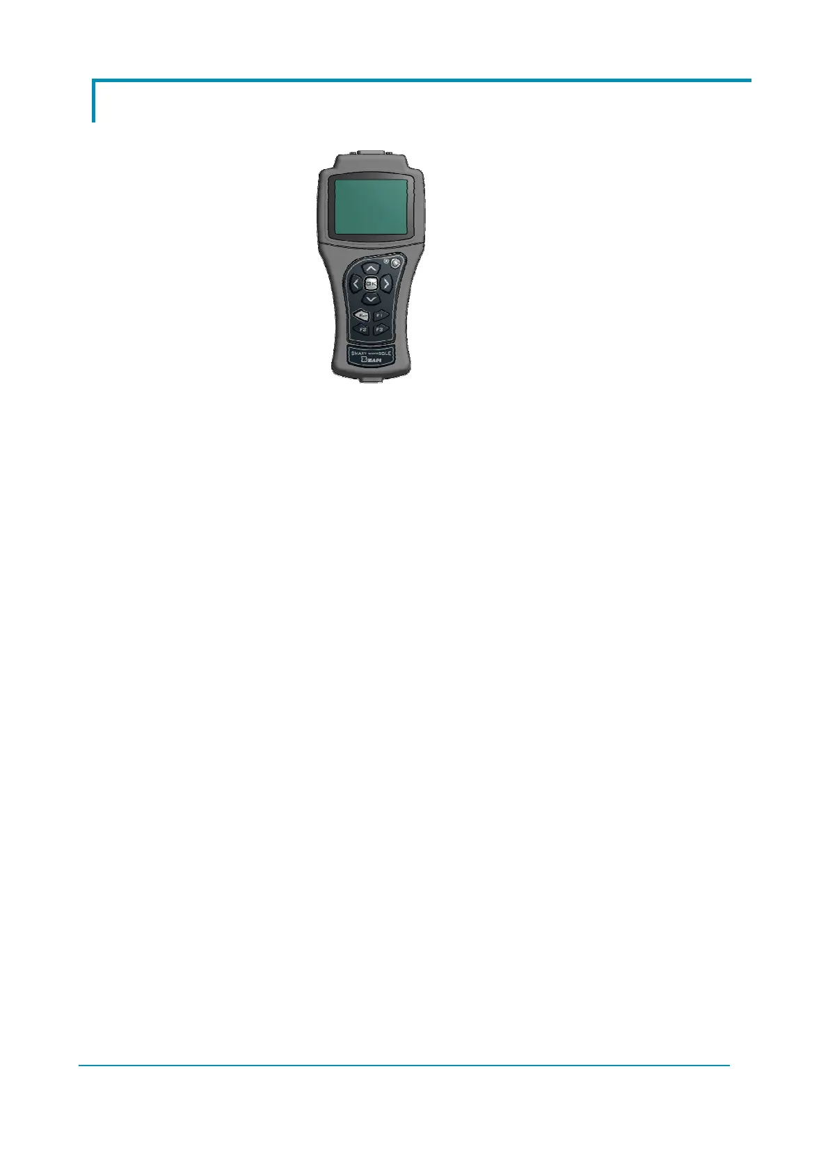
12.2 Appendix B: Zapi Smart Console user guide
12.2.1 Operational Modes
Smart Console has been designed to have multiple ways of operation. Three modes
can be identified:
Serial connection powered by four standard AA size batteries placed in the
battery holder of the console.
CAN bus connection powered by four standard AA size batteries placed in the
battery holder of the console.
CAN bus connection with Smart Console supplied by an external dc source. This
source may be a standard battery (lead-acid or other type) or a dc/dc converter
Current-loop serial connection
Smart Console offers the same serial connection as the well-known Console Ultra.
Main features of this operational mode are:
Current-loop serial communication.
Console is connected to a single controller only (even if Remote Console option
is available).
Selectable baud-rate.
Zapi can provide the serial cable compatible with Molex SPOX connector used in
Console Ultra.
CAN bus connection
The Smart Console can connect to an existing CAN line and connect with any Zapi
controller inside this line.
Main features of this operational mode:
It can be connected to a CAN line composed of any combination of modules,
both Zapi ones and non-Zapi ones;
Supported speeds: 125, 250, 500 kbps;
It sees the entire CAN line and all CAN modules.
 Loading...
