Page – 26/139 AFFZP0BB – ACE3 – User Manual
5.3 Accelerator unit
One analog input can be connected to an accelerator unit. The accelerator unit can
consist of a potentiometer or a Hall-effect device. It should be in a three-wire
configuration. The potentiometer is supplied through terminal A2 (positive terminal)
and A9 (negative terminal). Potentiometer output signal (from the wiper contact)
must drive input CPOT (A3) and voltage signal must be in the 0 – 10 V range.
Potentiometer resistance should be in the 0.5 k – 10 k range; generally, current
should be in the 1.5 – 30 mA range. Faults can occur if this limit is exceeded.
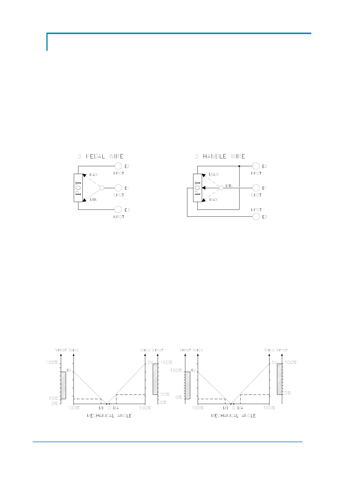
The standard connection for the potentiometer is the one on the left of next figure
(potentiometer at rest on one end) in combination with a couple of travel-demand
switches. On request, it is also possible to adopt the configuration on the right
(potentiometer at rest in the middle) in combination with a couple of travel-demand
switches.
The procedure for automatic acquisition of the potentiometer signal is carried out
using the Console, by means of the PROGRAM VACC function. This enables the
adjustment of the minimum and maximum useful levels, in both direction. This
function is particularly useful when it is necessary to compensate for asymmetry of
mechanical elements associated with the potentiometer, especially relating to the
minimum level.
The following two graphs show the output voltage of a potentiometer versus the
mechanical angle of the control lever. Angles MI and MA indicate the points where
the direction switches close, while 0 represents the mechanical zero of the lever, i.e.
its rest position. Also, the relationship between motor voltage (Vmot) and
potentiometer voltage (Vacc) is shown. After the adjustment procedure, Vmot
percentage is mapped over the useful voltage ranges of the potentiometer, for both
directions. On the other hand, before calibration it results mapped over the default
0 – 5 V range.
Before PROGRAM VACC After PROGRAM VACC
 Loading...
