AFFZP0BB – ACE3 – User Manual Page – 31/139
6.2.3 Wirings: CAN bus connections and possible interferences
4 CAN stands for Controller Area Network. It is a communication protocol for real time
control applications. CAN operates at data-rate of up to 1 Mbit/s.
It was introduced by the German company Bosch to be used in the automotive
industry to permit communication among the various electronic modules of a
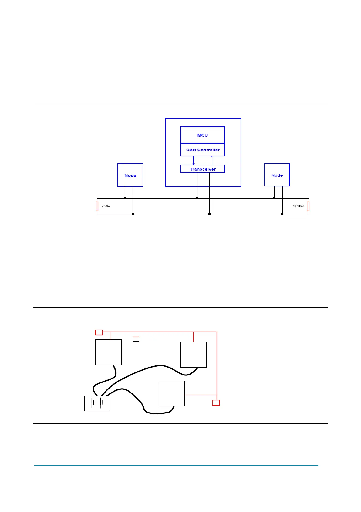
vehicle. The connection scheme is illustrated in the following image.
- The best type of cables for CAN connections is the twisted pair; if it is necessary
to increase the immunity of the system to disturbances, a good choice would be
to use shielded cables, where the shield is connected to the frame of the truck.
Sometimes it is sufficient a not shielded two-wire cable or a duplex cable.
- In a system like an industrial truck, where power cables carry currents of
hundreds of Ampere, voltage drops due to the impedance of the cables may be
considerable, and that could cause errors on the data transmitted through the
CAN wires. The following figures show an overview of wrong and right layouts
for the routing of CAN connected systems.
U Wrong Layout:
The red lines are CAN wires.
The black boxes are different modules, for example a traction controller, a pump
controller and a display connected via CAN bus.
Module
Module
Module
 Loading...
