Page – 32/139 AFFZP0BB – ACE3 – User Manual
The black lines are the power cables.
This is apparently a good layout, but actually it can bring to errors onto the CAN line.
The best solution depends on the type of nodes (modules) connected in the
network.
If the modules are very different in terms of power, then the preferable connection is
the daisy chain.
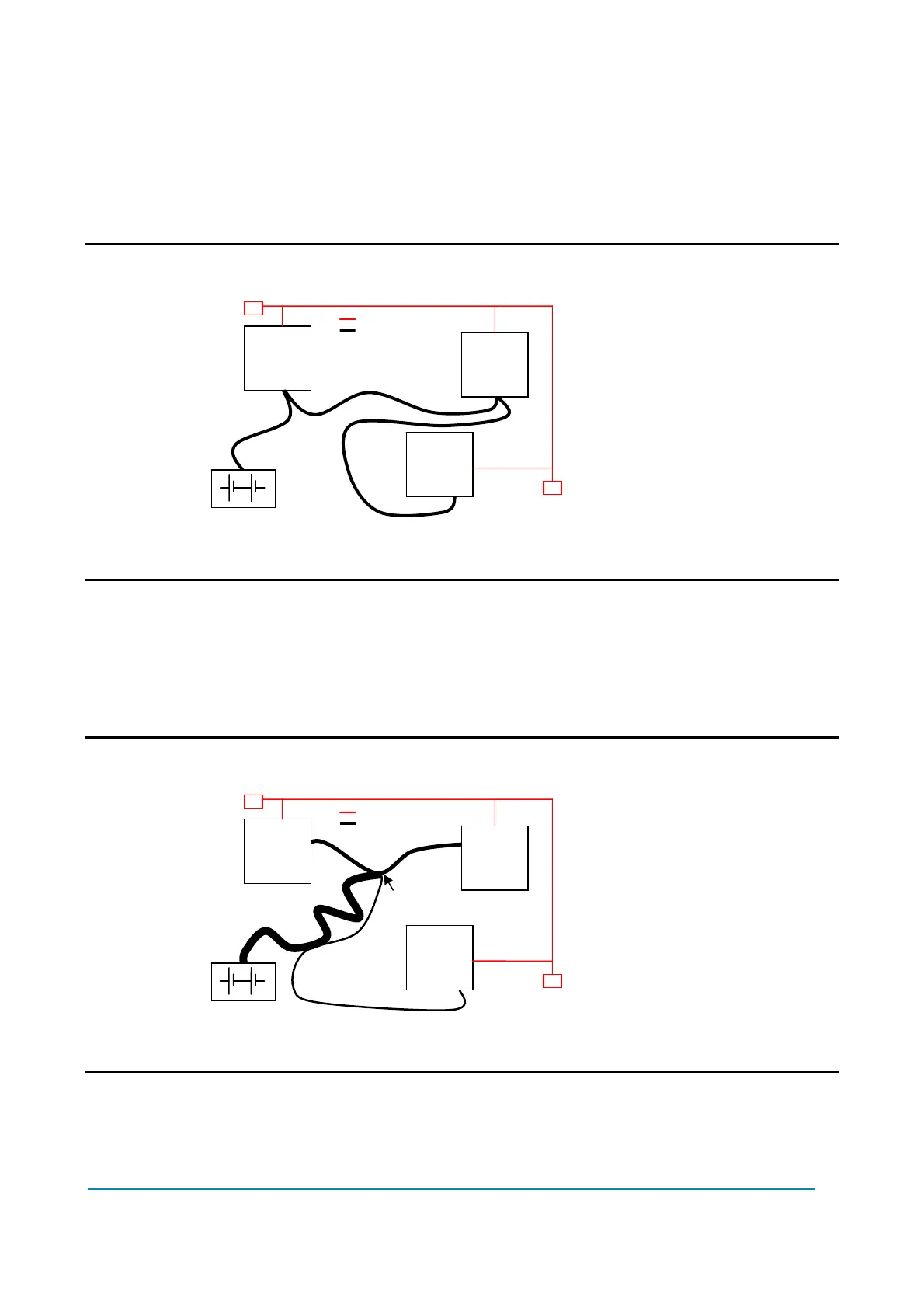
U Correct Layout:
Note: Module 1 power > Module 2 power > Module 3 power
The chain starts from the –BATT post of the controller that deals with the highest
current, while the other ones are connected in a decreasing order of power.
Otherwise, if two controllers are similar in power (for example a traction and a pump
motor controller) and a third module works with less current (for example a steering
controller), the best way to address this configuration is creating a common ground
point (star configuration), as it is in the next figure.
U Correct Layout:
Note: Module 1 power ≈ Module 2 power > Module 3 power
In this case, the power cables of the two similar controllers must be as short as
possible. Of course also the diameter of the cables concurs in the voltage drops
described before (a greater diameter brings to a lower impedance), so in this last
example the cable between negative battery terminal and the center of the ground
Module
Module
Module
Center of the Ground connectio
Module
Module
Module
 Loading...
