Page – 80/139 AFFZP0BB – ACE3 – User Manual
8.9 NLC & NEB output
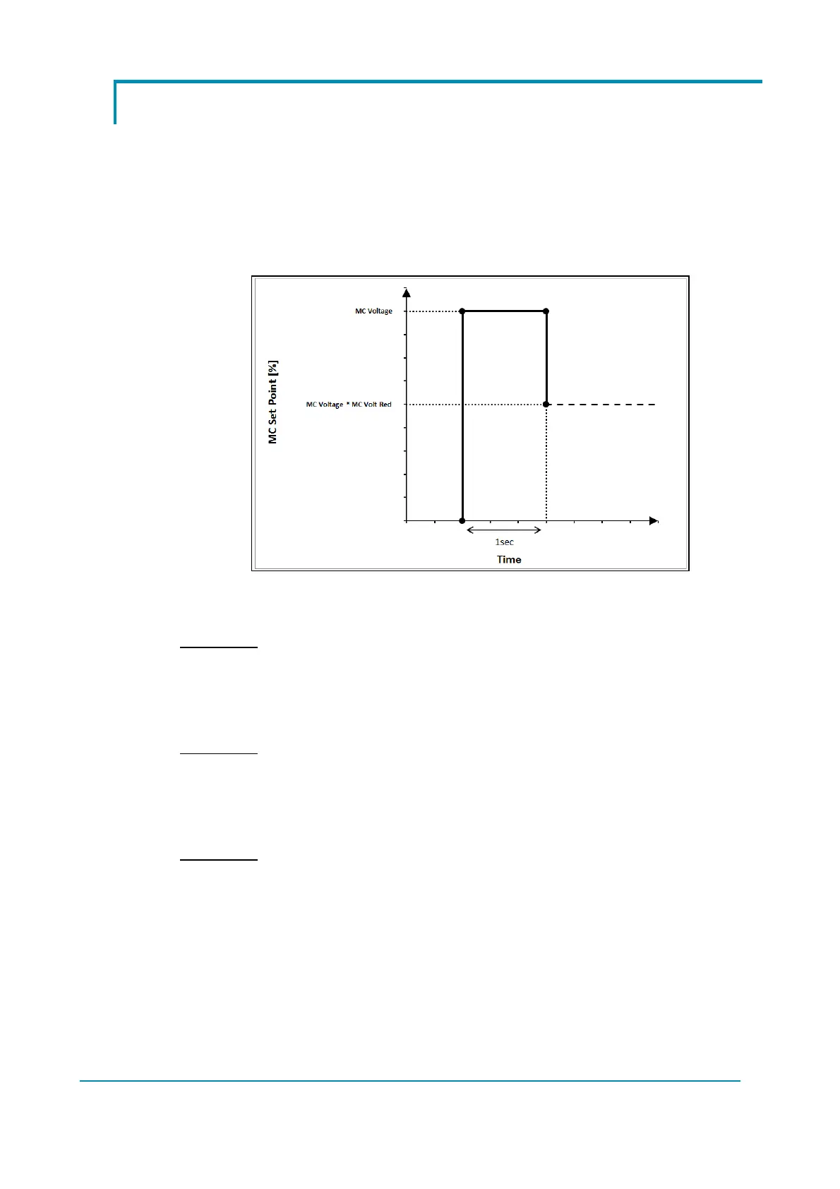
For the NLC output (A16) [or NEB output (A18)] there is the possibility to set a pull-
in voltage and to define a retention voltage continuously applied to the coil.
MC VOLTAGE [or EB VOLTAGE] parameter specifies the duty cycle applied in the
first second after key-on and MC VOLT RED [or EB VOLT RED] determines the
duty-cycle applied after that, necessary to keep the contactor closed [or brake
disengaged] according to this formula:
%
∙
Figure 3: NMC & NEB Output management
Example 1:
MC VOLTAGE = 100%
MC VOLTAGE RED = 70%
The contactor is closed by applying 100% of duty-cycle to the coil and then then it is
reduced to 70%.
Example 2:
MC VOLTAGE = 70%
MC VOLTAGE RED. = 100%
The contactor is closed by applying 70% of duty-cycle to the coil and then it is kept
at the same value.
Example 3:
MC VOLTAGE = 70%
MC VOLTAGE RED = 70%
The contactor is closed by applying 70% of duty-cycle to the coil and then it is
reduced to 49% (70% of 70%).
 Loading...
