35
Application Macro Motor Potentiometer
This macro provides a cost-effective interface for PLCs that vary the speed of
the drive using only digital signals.
The value of parameter 9902 is 4.
*Note!
• If both DI 3 and DI 4 are active or inactive, reference is kept stable.
• Reference is stored during stop or power down condition.
• Analogue reference is not followed when motor potentiometer is
selected.
Motor potentiometer parameter values:
Input signals Output signals
• Start, stop and direction (DI1,2) • An. output AO: Frequency
• Reference up (DI3) • Relay output 1: Fault
• Reference down (DI4) • Relay output 2: Running
• Preset speed selection (DI5)
1001
EXT 1 COMMANDS 2 (DI1,2) 1106 EXT REF2 SELECT 0 (KEYPAD)
1002
EXT 2 COMMANDS 0 (NOT SEL) 1201 CONST SPEED SEL 5 (DI5)
1003
DIRECTION 3 (REQUEST) 1601 RUN ENABLE 0 (NOT SEL)
1102
EXT1/EXT2 SEL 6 (EXT1) 2105 PREMAGN SEL 0 (NOT SEL)
1103
EXT REF1 SELECT 6 (DI3U,4D) 2201 ACC/DEC 1/2 SEL 0 (NOT SEL)
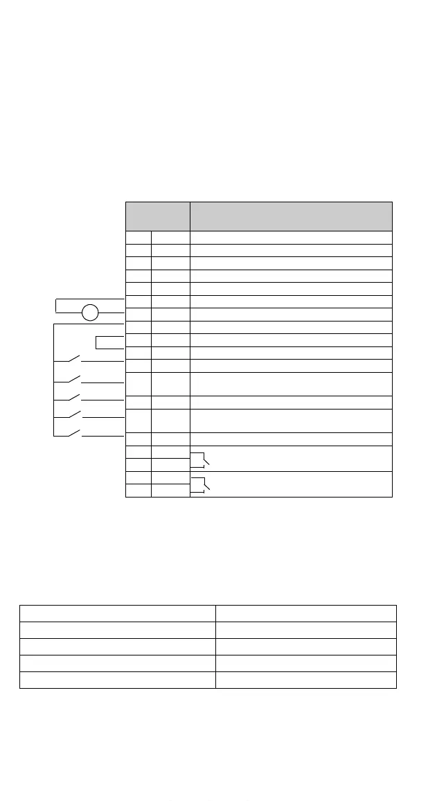
Control
Terminal s
Function
1SCR
2 AI 1 Not used
3AGND
4 10 V Reference voltage 10 VDC
5 AI 2 Not used
6AGND
7 AO Output frequency 0...20 mA <=> 0...50 Hz
8AGND
9 +12 V +12 VDC
10 DCOM
11 DI 1 Start/Stop: Activate to start ACS140
12 DI 2 Forward/Reverse: Activate to reverse rotation
direction
13 DI 3 Reference up: Activate to increase reference*
14 DI 4 Reference down: Activate to decrease
reference*
15 DI 5 Constant speed 1
16 RO 1A Relay output 1
Fault: open
17 RO 1B
18 RO 2A Relay output 2
Running: closed
19 RO 2B
mA
www.barghmaher.org

 Loading...


