62
Group 26: Motor Control
Code Description
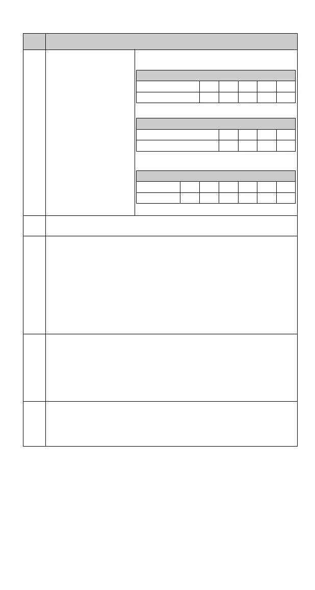
2603 IR COMPENSATION
IR compensation voltage at
0Hz.
Note! IR compensation
should be kept as low as
possible to prevent
overheating.
Refer to Table 4.
Table 4 Typical IR compensation values.
2604 IR COMP RANGE
IR compensation range. Defines frequency after which IR compensation is 0 V.
2605 LOW NOISE
Motor acoustical noise option.
0 =
STANDARD (switching frequency 4 kHz)
1 =
LOW NOISE (switching frequency 8 kHz)
2 =
SILENT (switching frequency 16 kHz)
Note! When the low noise (8 kHz) setting is used, the maximum loadability of
the ACS140 is I
2
at 30 °C ambient temperature or 0.9 * I
2
at 40 °C. When the
silent (16 kHz) setting is used, the maximum loadability is 0.75 * I
2
at 30 °C
ambient temperature. (except ACS143-1K1-3, ACS143-2K1-3, ACS143-1H1-3
and ACS143-2H1-3 then the maximum loadability is 0.55 * I
2
at 30 °C.)
2606 U/F RATIO
U/f ratio below field weakening point.
1 =
LINEAR
2 = SQUARE
Linear is preferred for constant torque applications and Square for centrifugal
pump and fan applications. (Square is more silent for most operating
frequencies.)
2607 SLIP COMP RATIO
A squirrel-cage motor will slip under load. The slip can be compensated by
increasing the frequency as the motor torque increases. This parameter defines
the gain for the slip. 100 % means full slip compensation; 0 % means no slip
compensation.
200 V Units
P
N
/ kW 0.12 0.18 0.25 0.37 0.55
IR comp / V 30 27 25 23 21
200 V Units
P
N
/ kW 0.75 1.1 1.5 2.2
IR comp / V 18 16 14 13
400 V Units
P
N
/ kW 0.37 0.55 0.75 1.1 1.5 2.2
IR comp / V373330272523
www.barghmaher.org

 Loading...


