73
Group 40: PID Control
The PID Control Macro allows the ACS140 to take a reference signal
(setpoint) and an actual signal (feedback), and automatically adjust the speed
of the drive to match the actual signal to the reference. Figure 26 on page 96
(APPENDIX) shows the connections of internal signals when the PID Control
macro is selected.
Code Description
4001 PID GAIN
This parameter defines the gain of the PID Controller. The setting range is
0.1... 100. If you select 1, a 10 % change in error value causes the PID
Controller output to change by 10 %.
* Limited by parameter 2008
MAXIMUM FREQ.
4002 PID INTEG TIME
PID controller integration time. Defined as the time in which the maximum
output is achieved if a constant error value exists and the gain is 1. Integration
time 1 s denotes that a 100 % change is achieved in 1 s.
4003 PID DERIV TIME
PID controller derivation time. If the process error value changes linearly, D part
adds a constant value into the PID controller output. The derivative is filtered
with a 1-pole filter. The time constant of the filter is defined by parameter 4004
PID DERIV FILTER.
4004 PID DERIV FILTER
Time constant for the filter of D part. By increasing the filter time constant it is
possible to smooth the effect of the D part and suppress noise.
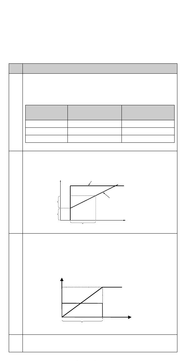
Table 5 Effect of gain when MAXIMUM FREQ is 50 Hz.
PID Gain
Frequency Change for a
10 % Change in Error
Frequency Change for
a 50 % Change in Error
0.5 2.5 Hz 12.5 Hz
1.0 5 Hz 25 Hz
3.0 15 Hz 50 Hz *
Control deviation
PID Controller Output
Gain
Gain
PID Integration Time
t
t
PID derivation time
Gain
Process Error Value
100 %
www.barghmaher.org