Mechanical installation of non-pre-assembled units (ACS800-04M)
104
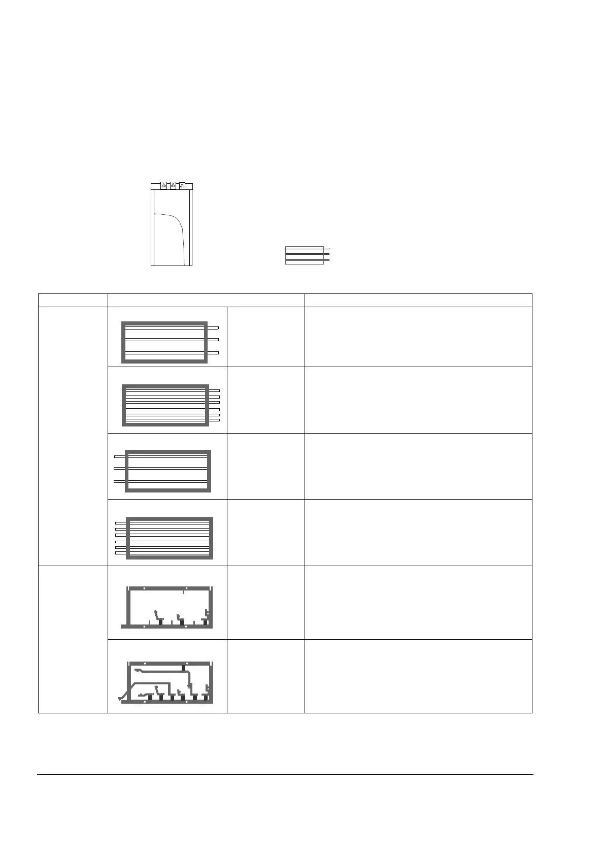
Assembling procedure for units with busbars on the short side (+H360)
Working order
References to instructions in this chapter are printed in italic in the table below. The
pictures represent frame size R7 with the following orientations.
Step If Instruction
1
Preparing
the pedestal
AC busbars on
the right side
Go to step 2.
AC busbars, R-,
R+/UDC+ and
UDC- busbars on
the right side
(+H356 required)
1. See Connecting the DC busbars to the pedestal
(+H360 +H356 only) on page 107.
2.Go to step 2.
AC busbars on
the left side
1. See Swapping the pedestal output busbars to the
left-hand side on page 106.
2.Go to step 2.
AC busbars, R-,
R+/UDC+ and
UDC- busbars on
the left side
(+H356 required)
1. See Swapping the pedestal output busbars to the
left-hand side on page 106.
2. See Connecting the DC busbars to the pedestal
(+H360 +H356 only) on page 107.
3.Go to step 2.
2
Preparing
the adapter
AC busbars on
the right or left
side
Go to step 3.
AC busbars, R-,
R+/UDC+ and
UDC- busbars on
the right or left
side
(+H356 required)
1. See Preparing the adapter (+H360 +H356 only) on
page 108.
2.Go to step 3.
Front
RightLeft
Pedestal viewed from above
V2
U2
W
W2
V2
U2

 Loading...


