Mechanical installation of non-pre-assembled units (ACS800-04M)
76
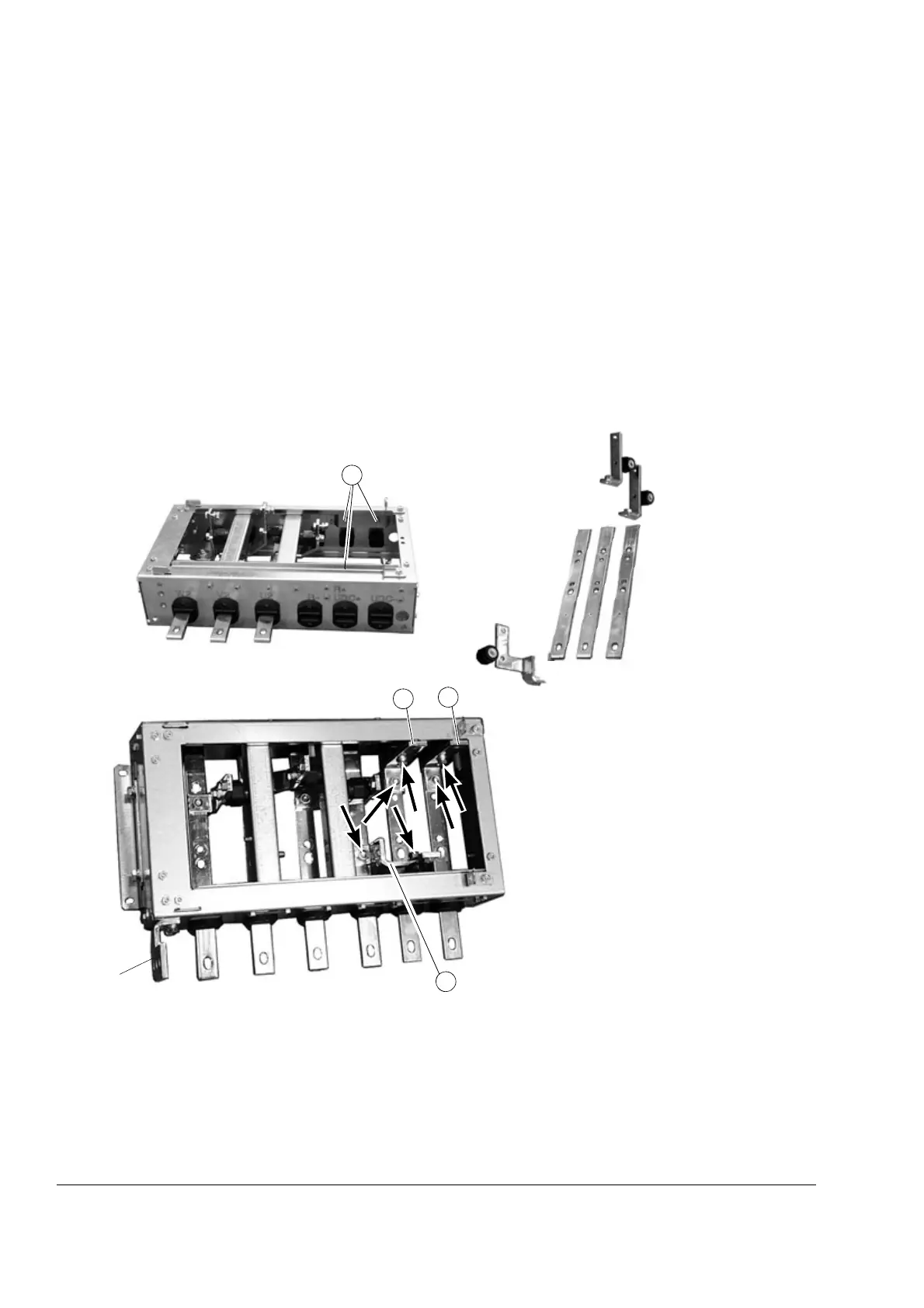
Connecting the DC busbars to the pedestal (+H356 and +H363 only)
Procedure
1. Screw insulating supports (“a” below) onto the free pins (“b” below) on the inner
sides of the pedestal.
2. Push busbars (c) through the R-, R+/UDC+ and UDC- lead-through insulators as
the W2, V2 and U2 busbars.
3. Connect the connecting busbars (d, e, f) to the insulating supports and to the R-,
R+/UDC+ and UDC busbars as shown below.
For +H363, see also Optional selection +H363 on page 79.
Photos of frame size R7
a
c
R-
R+
UDC+
UDC-
d
e
f
a
a
DC busbars connected
PE busbar
b
d
e
f

 Loading...


