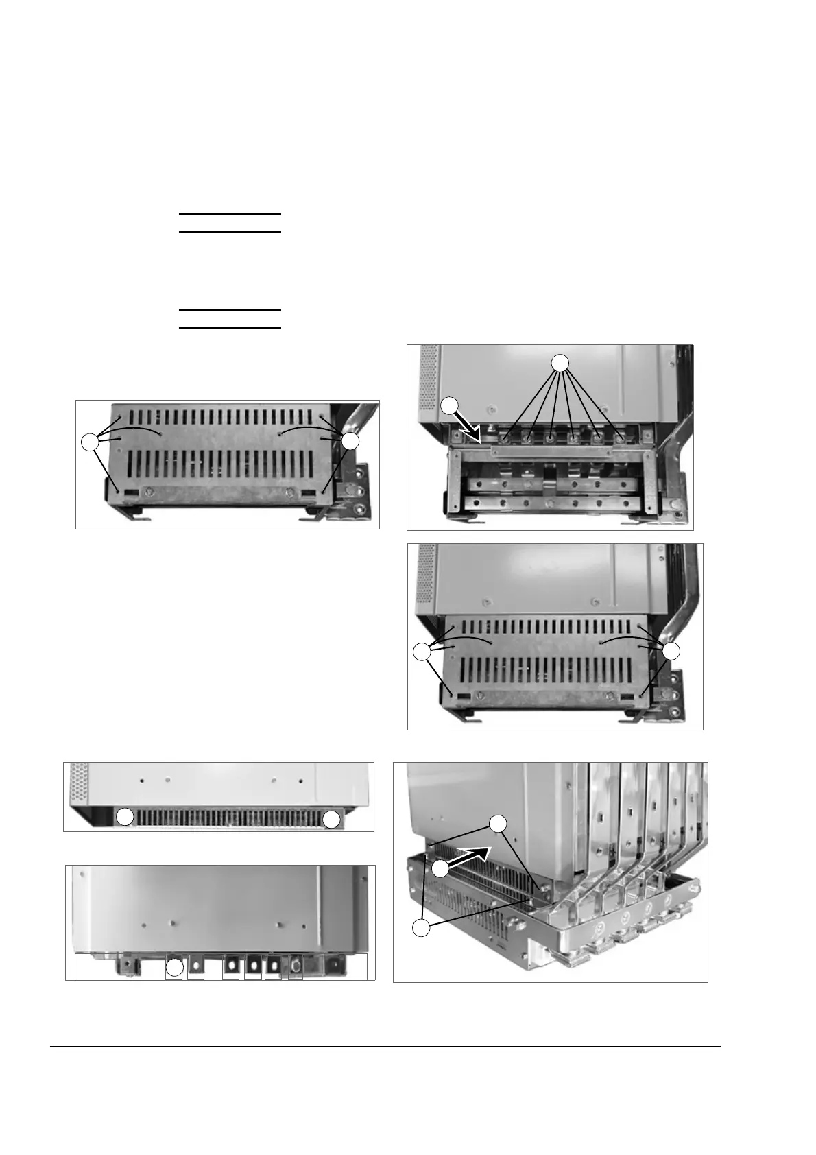
Mechanical installation of non-pre-assembled units (ACS800-04M)
110
Fastening the drive module to the pedestal via the adapter
The DC busbars (+H356) are included in the installation examples below. The
adapter has been connected to the drive module.
1. Frame size R7:
Remove the “long front” side plate of the pedestal.
Frame size R8:
Remove the “long front” side plate of the adapter.
2. Slide the drive module with the adapter fastened onto the pedestal.
3. Connect the busbars.
4. Frame size R7:
Fasten the side plate of the pedestal.
Frame size R8:
Fasten the side plate to the adapter and the pedestal.
4
4
Frame size R8
Frame size R7
1
1
3
4
4
M6
M6
M5
M5
M5
2
1
1
3
2

 Loading...


