Planning the cabinet installation
27
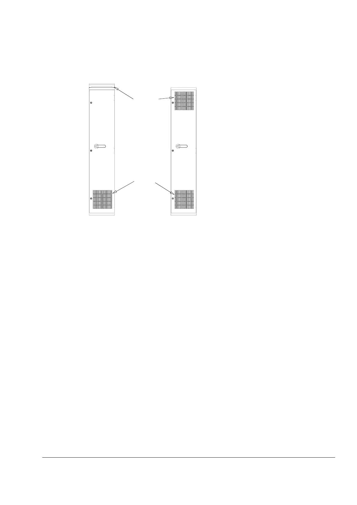
The drawing below shows two typical cabinet cooling solutions. The air inlet is at the
bottom of the cabinet, while the outlet is at the top, either on the upper part of the
door or on the roof.
The internal cooling fans of the converter modules and reactors/chokes are usually
sufficient to keep the component temperatures low enough in IP 22 cabinets.
In IP 54 cabinets, thick filter mats are used to prevent water splashes from entering
the cabinet. This entails the installation of additional cooling equipment, such as a
hot air exhaust fan.
Arrange the cooling air flow through the converter module so that the requirements
given in chapter Technical data in ACS800-04/04M/U4 Hardware Manual
[3AFE64671006 (English)] are met:
• cooling air flow
Note:
The figures apply to continuous nominal load. If the load is cyclic or less than nominal, less
cooling air is required.
• allowed ambient temperature.
See section Cabinet cooling data for:
• allowed temperature rise inside the cabinet
• allowed pressure drop over the cabinet that the module fan can overcome
• air inlet and outlet sizes required for the module cooling and recommended filter
material (if used).
Air inlet
Air outlet

 Loading...


