Home
ABB
Controller
ACS800-04
ABB ACS800-04 User Manual
4
of 1
of 1 rating
162 pages
Give review
Manual
Specs
To Next Page
To Next Page
To Previous Page
To Previous Page
Loading...
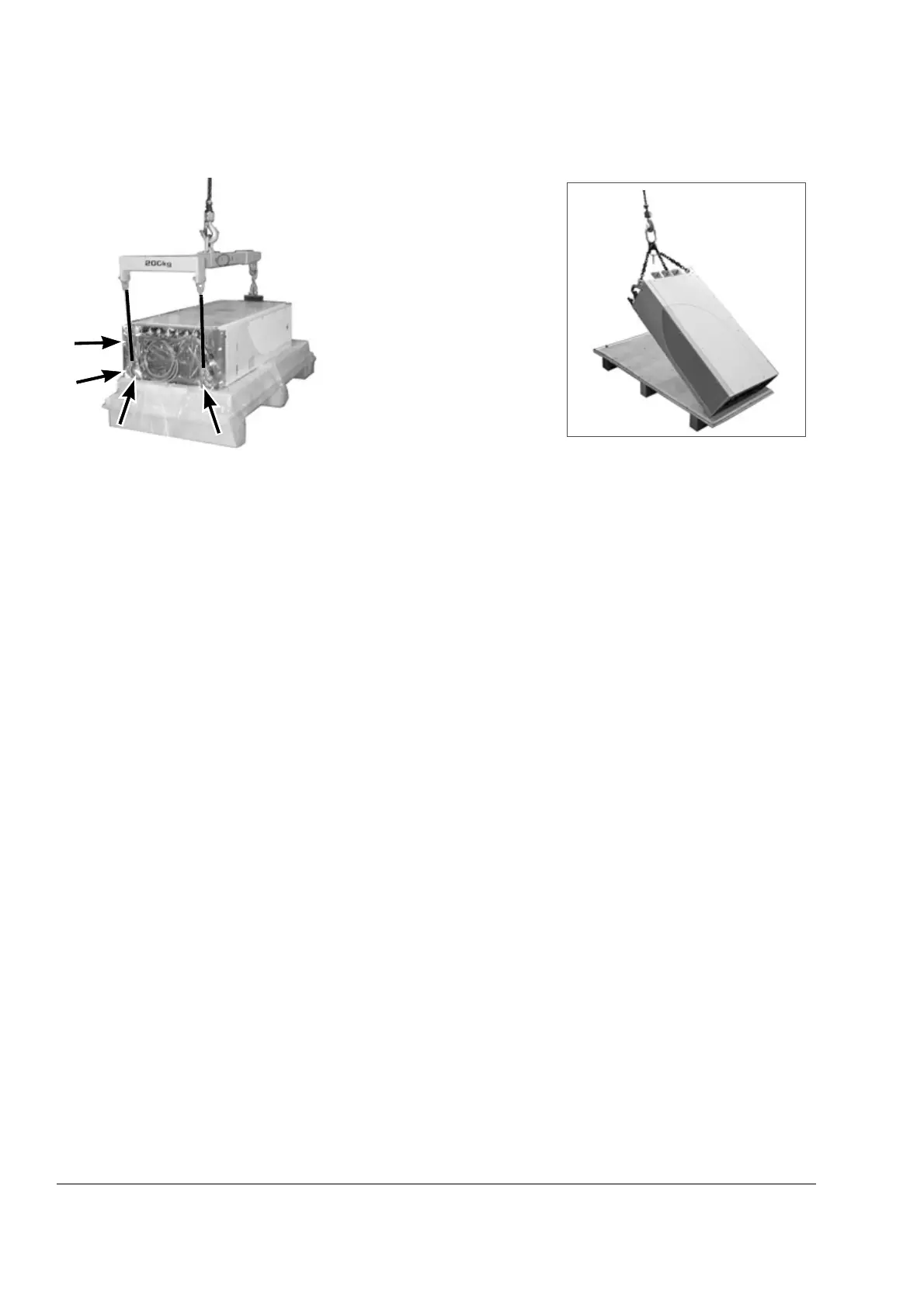
Mechani
cal ins
tallat
ion of non-
pre-a
ssemble
d units (
ACS800-
04M)
48
Fasten th
e lifting hoo
ks to the lif
ting
lugs of the
drive modu
le. A hook c
an
be faste
ned to the
base bra
cket also.
Use a
t le
ast
three
fas
ten
ing
points
because
the module is
turns ove
r
easi
ly
.
47
49
Table of Contents
Default Chapter
2
ACS800 Single Drive Manuals
2
Table of Contents
5
Table of Contents
11
About this Manual
11
What this Chapter Contains
11
Target Audience
11
Safety
11
Other Related Manuals
11
Categorization According to the Frame Size
12
Categorization According to the Plus Code
12
Contents
12
Installation, Commissioning and Operating Flowchart
13
Product and Service Inquiries
14
Product Training
14
Providing Feedback on ABB Drives Manuals
14
The ACS800-04/U4 and ACS800-04M
15
What this Chapter Contains
15
The ACS800-04/U4
15
The ACS800-04M
16
Example Configurations
16
Type Designation Label
17
Type Code
18
Main Circuit and Control Interfaces
20
Connections of the Drive Control Unit (RDCU) in Frame Sizes R7 and R8
21
Operation
21
Printed Circuit Boards
22
Motor Control
22
Planning the Cabinet Installation
23
What this Chapter Contains
23
Cabinet Construction
23
Disposition of the Devices
23
Layout Examples, Door Closed
24
Layout Examples, Door Open
25
Grounding of Mounting Structures
26
Busbar Material and Joints
26
Tightening Torques
26
Cabinet Cooling
26
Cabinet Cooling Data
28
IP 22 Cabinet with no Extra Fan
28
IP 54 Cabinet with an Extra Fan
28
Preventing the Recirculation of Hot Air
29
Outside the Cabinet
29
Inside the Cabinet
29
Cubicle Heaters
29
Required Free Space Around the Drive Module for Cooling
30
Free Space at the Top of the Drive Module
30
Free Space Around Units with Busbars on the Long Side (Bookshelf Mounting +H354)
31
Free Space Around Units with Busbars on the Short Side (Flat Mounting +H360)
32
When the Drive Module Is Installed in Another Position than Vertically
33
Drive Module of Frame Size R7 on Its Side
33
Drive Module of Frame Size R7 on Its Back
34
EMC Requirements
35
Grounding of Cable Shields
36
Installing the Drive Control Unit (RDCU)
36
Fastening of the Control Panel (CDP312R)
37
Installing the Control Panel Directly on the Cabinet Door
37
Control Panel Mounting Platform RPMP-11/13 (+J410)
37
Control Panel Holder RPMP-21 (+J413)
38
Mechanical Installation of Pre-Assembled Units (ACS800-04/U4)
39
What this Chapter Contains
39
Moving and Unpacking the Unit
39
Delivery Check
40
Required Tools
41
Installation Procedure
42
Fasten the Module to the Cabinet
42
Clamping the Pedestal with the Outside Brackets
42
Fasten the Terminals to the Busbars
42
View of Output Busbar Connections of Frame Size R7 (DC and Brake Busbars Included)
43
View of Output Busbar Connections of Frame Size R8 (DC and Brake Busbars Included)
44
User Connections of Prevention of Unexpected Start (+Q950)
44
Mechanical Installation of Non-Pre-Assembled Units (ACS800-04M)
45
What this Chapter Contains
45
How to Read this Chapter
45
Units with Bottom Exit
45
Units with Pedestal and Busbars on the Long Side (+H354, Bookshelf Mounting)
45
Units with Pedestal and Busbars on the Short Side (+H360, Flat Mounting)
45
Required Tools and Tightening Torques
46
Moving and Unpacking the Unit
46
Frame Size R7 Units with Bottom Exit (+H352)
49
Delivery Check
49
Assembling Procedure
53
Fastening the Spacer
55
Fastening the Top Entry Busbar and Bottom Exit Shrouds (+B060)
55
Top Entry Busbar Shroud
55
Bottom Exit Shroud
56
Units with Pedestal and Busbars on the Long Side (+H354, Bookshelf Mounting)
57
Delivery Check
57
Item Packages
57
Item Packages of Frame Size R7 with Busbars on the Long Side
58
Item Packages of Frame Size R8 with Busbars on the Long Side
64
Assembling Procedure for Units with Busbars on the Long Side (+H354)
73
Working Order
73
Connecting the DC Busbars to the Pedestal (+H356 and +H363 Only)
76
Procedure
76
Photos of Frame Size R7
76
Photos of Frame Size R8
77
Busbars to the Left- or Right-Hand Side of the Module
78
Swapping the Busbars of the Pedestal to the Other Side
78
Optional Selection +H363
79
Fastening the Pedestal to the Cabinet Base (Not for Wall-Mounted Units)
80
Clamping the Pedestal with the Outside Brackets
80
Fastening the Pedestal through the Holes Inside the Pedestal
80
Fastening the Drive Module by Top to the Cabinet Frame
81
Fastening the Drive Module to Wall (Wall-Mounted Units Only, Not for Base-Mounted Units)
81
Requirements for Protection
81
Requirements for the Wall
81
Floor
81
Procedure
82
Fastening the Output Busbars and PE Terminal and Sliding the Module in
86
View of Output Busbar Connections of Frame Size R7 (DC and Brake Busbars Included)
87
View of Output Busbar Connections of Frame Size R8 (DC and Brake Busbars Included)
88
Fastening the Drive Module to the Pedestal
89
Fastening the Shrouds in Frame Size R8
90
Top Entry Busbar Shroud
90
Vertical Busbar Shroud
90
Units with Pedestal and Busbars on the Short Side (+H360, Flat Mounting)
91
Delivery Check
91
Item Packages
91
Item Packages of Frame Size R7 with Busbars on the Short Side
92
Item Packages of Frame Size R8 with Busbars on the Short Side
98
Assembling Procedure for Units with Busbars on the Short Side (+H360)
104
Working Order
104
Swapping the Pedestal Output Busbars to the Left-Hand Side
106
Connecting the DC Busbars to the Pedestal (+H360 +H356 Only)
107
Required Parts
107
Procedure
107
Preparing the Adapter (+H360 +H356 Only)
108
Required Parts
108
Procedure
108
Fastening the Adapter to the Drive Module
109
Fastening the Drive Module to the Pedestal Via the Adapter
110
Connecting the Output Busbars on the Short Side of the Module
111
Procedure for Frame Size R7
111
Procedure Frame Size R8
113
Checking the Installation
115
What this Chapter Contains
115
Visual Inspection
115
Cabinet Construction
115
Instrumentation, Busbars and Cabling
115
Groundings and Protection
117
Labels, Switches, Fuses and Doors
118
Dimensional Drawings
119
Frame Size R7 Without Pedestal (MM)
120
Frame Size R7 with Bottom Exit (MM)
121
Frame Size R7 with Bottom Exit and Top Entry and Bottom Exit Shrouds (MM)
122
Frame Size R7 with Busbars on the Left Side (MM)
123
Frame Size R7 with DC Busbars on both Sides (MM)
124
Frame Size R7 Pedestal Busbars on the Long Side (MM)
125
Frame Size R7 with Busbars on the Short Side (MM)
126
Frame Size R8 Without Pedestal (MM)
127
Frame Size R8 with Busbars on the Left Side (MM)
128
Frame Size R8 with Top Entry and Vertical Busbar Shrouds (MM)
129
Frame Size R8 with Busbars on both Sides (MM)
130
Frame Size R8 Pedestal Busbars on the Long Side (MM)
131
Frame Size R8 with Busbars on the Short Side (MM)
132
Wall Mounting Spacers
133
Frame Size R7 Bottom Exit Kit (+H352)
134
Frame Size R7 Top Entry Busbar Shroud and Bottom Exit Shroud (+B060)
135
Control Panel Holder RPMP-21 (+J413)
136
Drive Control Unit (RDCU-02)
137
Dimensional Drawings (USA)
138
Frame Size R7 Without Pedestal (Inches)
139
Frame Size R7 with Bottom Exit (Inches)
140
Frame Size R7 with Bottom Exit and Top Entry and Bottom Exit Shrouds (Inches)
141
Frame Size R7 with Busbars on the Left Side (Inches)
142
Frame Size R7 with Busbars on both Sides (Inches)
143
Frame Size R7 Pedestal Busbars on the Long Side (Inches)
144
Frame Size R7 with Busbars on the Short Side (Inches)
145
Frame Size R8 Without Pedestal (Inches)
146
Frame Size R8 with Busbars on the Left Side (Inches)
147
Frame Size R8 with Top Entry and Vertical Busbar Shrouds (Inches)
148
Frame Size R8 with Busbars on both Sides (Inches)
149
Frame Size R8 Pedestal Busbars on the Long Side (Inches)
150
Frame Size R8 with Busbars on the Short Side (Inches)
151
Circuit Diagrams
153
What this Chapter Contains
153
Assembly Drawings
155
What this Chapter Contains
155
Adding UDC+/R+, UDC- and R- Busbars to the Pedestal (Frame Size R7, +H356+H360)
156
Adding UDC+/R+, UDC- and R- Busbars to the Adapter (Frame Size R7, +H356+H360)
157
Adding UDC+/R+, UDC- and R- Busbars to the Pedestal (Frame Size R8, +H356+H360)
158
Adding UDC+/R+, UDC- and R- Busbars to the Adapter (Frame Size R8, +H356+H360)
159
Other manuals for ABB ACS800-04
Hardware Manual
146 pages
Application Guide
46 pages
Installation
52 pages
4
Based on 1 rating
Ask a question
Give review
Questions and Answers:
Need help?
Do you have a question about the ABB ACS800-04 and is the answer not in the manual?
Ask a question
ABB ACS800-04 Specifications
General
Brand
ABB
Model
ACS800-04
Category
Controller
Language
English
Related product manuals
ABB ACS800-01
180 pages
ABB ACS800-04M
162 pages
ABB ACS800-37-0060-3
228 pages
ABB ACS800-37-0170-3
228 pages
ABB ACS800-37-0170-7
228 pages
ABB ACS800-17
236 pages
ABB ACS800-U4
144 pages
ABB ACS800-U1
180 pages
ABB ACS800 Series
214 pages
ABB ACS800 Multidrive
22 pages
ABB ACS880-04
418 pages
ABB ACS880-04XT
664 pages

 Loading...


