HVC 450 kW E-Bus Charger Installation Guide
Revision: 1.2 COMPANY CONFIDENTIAL
Date released: 16-08-2018 Page 75 of 128
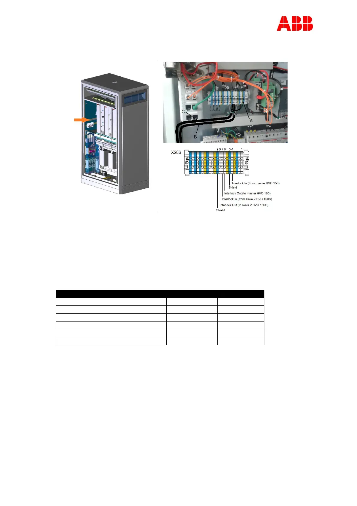
Interlock cable connection in slave 1 HVC 150S:
A Terminal block
B Interlock cable from/to slave 2 HVC 150S
C Interlock cable from/to master HVC 150
1. Move the cables towards the terminal block (A).
2. Strip 0.43 Inch of the insulation from the ends of the wires.
3. Crimp a ferrule onto the end of the wire.
4. Loosen the connector screws.
5. Insert the wires into the connectors, see table below:
Interlock In (master HVC 150)
Interlock Out (master HVC 150)
Interlock GND (master HVC 150)
Interlock In (slave 2 HVC 150S)
Interlock Out (slave 2 HVC 150S)
Interlock GND (slave 2 HVC 150S)
See also Appendix H Signal connection diagram.
6. Tighten the connector screws.
 Loading...