28 PositionMaster EDP300 DIGITAL POSITIONER | OI/EDP300-EN REV. D
… 7 Installation
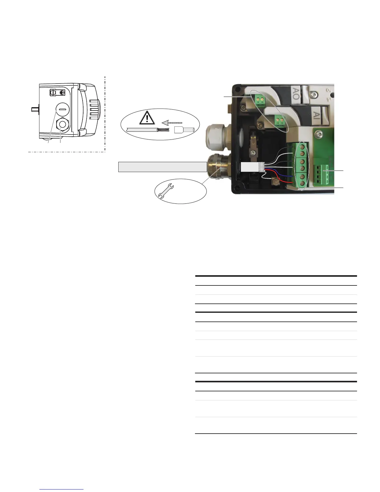
… Electrical connections
Connection on the device
M10950
M 20 mm /
1/2"NPT
1 2
3
4
5
1 Blind plug
2 Cable gland
3 Terminals for options modules
4 Terminals attachment set for digital feedback
5 Terminals basic device
Figure 22: Connection on device (example)
Change from one to tw o columns
2 tap holes ½- 14 NPT or M20 × 1.5 are provided on the left side
of the housing for cable entry in the housing. One of the tap
holes is fitted with a cable gland, while the other tap hole has a
blind plug.
Note
The connecting terminals are delivered closed and must be
unscrewed before inserting the wire.
1. Strip the wires to approximately 6 mm (0.24 in).
2. Connect the wires to the connecting terminals in line with
the connection diagram.
Wire cross-sectional areas
Basic device
Electrical connections
4 to 20 mA input Screw terminals max. 2.5 mm
2
(AWG14)
Options Screw terminals max. 1.0 mm
2
(AWG18)
Cross section
Rigid / flexible wires 0.14 to 2.5 mm
2
(AWG26 to AWG14)
Flexible with wire end sleeve 0.25 to 2.5 mm
2
(AWG23 to AWG14)
Flexible with wire end sleeve no
plastic sleeve
0.25 to 1.5 mm
2
(AWG23 to AWG17)
Flexible with wire end sleeve
with plastic sleeve
0.14 to 0.75 mm
2
(AWG26 to AWG20)
Multi-wire connection capacity (two wire with the same cross-section)
Rigid / flexible wires 0.14 to 0.75 mm
2
(AWG26 to AWG20)
Flexible with wire end sleeve no
plastic sleeve
0.25 to 0.75 mm
2
(AWG23 to AWG20)
Flexible with wire end sleeve
with plastic sleeve
0.5 to 1.5 mm
2
(AWG21 to AWG17)

 Loading...


