Section-6
04-3004_S6_OPM_ABB_POWERSCALE_10-50 kVA_EN_150113.doc Page 4/6 ABB
Printed in Switzerland – Modifications reserved
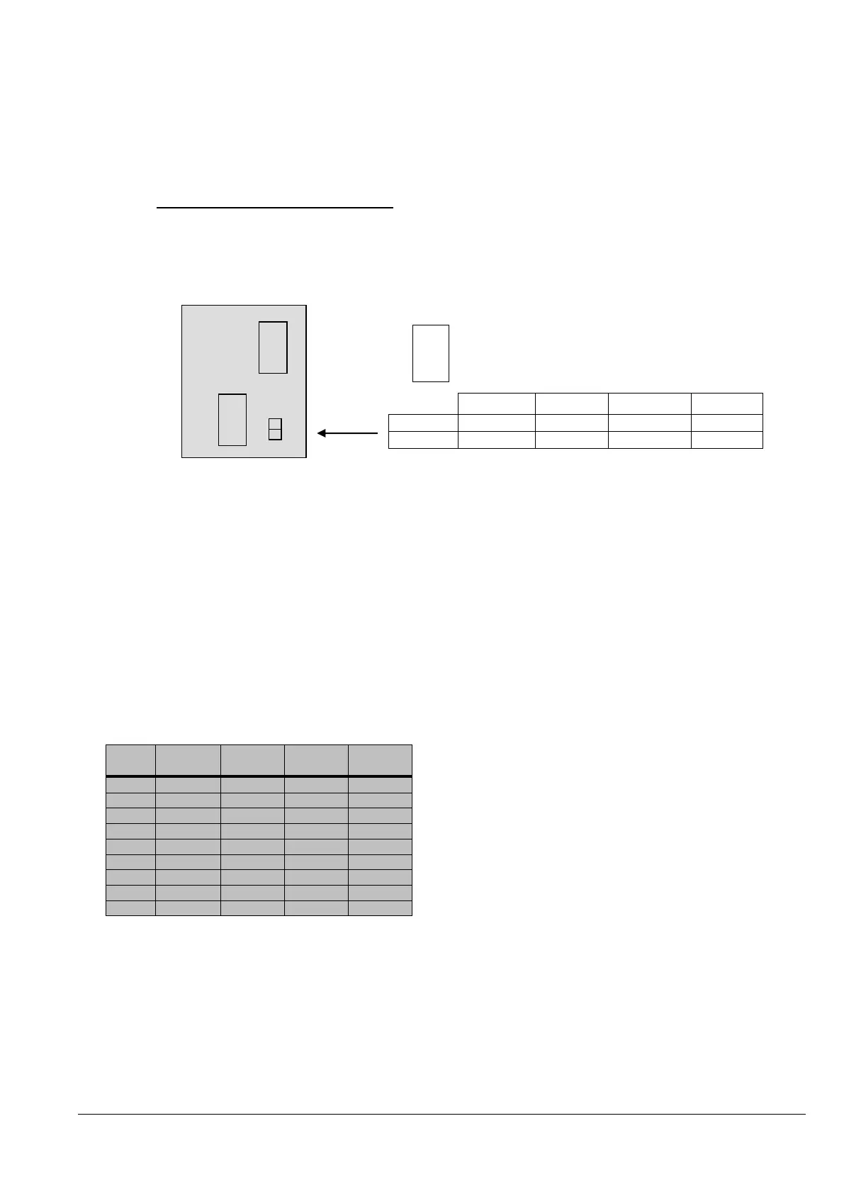
6.1.2.2.2 Parallel Adapter and DIP-Switch SW2-2
If the UPS-CABINETS are paralleled the Parallel Adapter will be placed on the Connector JD8 on the
distribution panel and the communications cables between the cabinets will be connected through the
connectors JD5 and JD6, as we are doing now.
NOTE: set the Switch SW2-2 correctly according to the corresponding cabinet configuration.
6.1.2.3 DIP-Switch SW1-9 Settings
Before starting up the parallel system it is necessary to set the DIP Switches SW1-9 to their correct positions.
6.1.2.4 DIP Switch SW1-9
The DIP Switch SW1-9 is located on every Cabinet (POWERSCALE) With this switch it is possible to
determine the “position of an POWERSCALE - Cabinet” in a Multi-Cabinet Chain. Define each
POWERSCALE - Cabinet in a Multi-Cabinet Chain as:
1. The “First”,
2. The “Middle” (there may be more than one) and
3. The “Last”
Cabinet in the Multi-Cabinet Chain by setting the DIP Switch SW1-9 on each cabinet according to the Table
below:
After having set the SW1-9 on all the POWERSCALE - Cabinets correctly the UPS’s may be commissioned
Parallel
Adapter
JD 5
SW2-2
JD6
 Loading...