Mounting
22 - EN FEX300, FEX500 CI/FEX300/FEX500-EN
Change from one to two colu mns
4.5 Installation Requirements
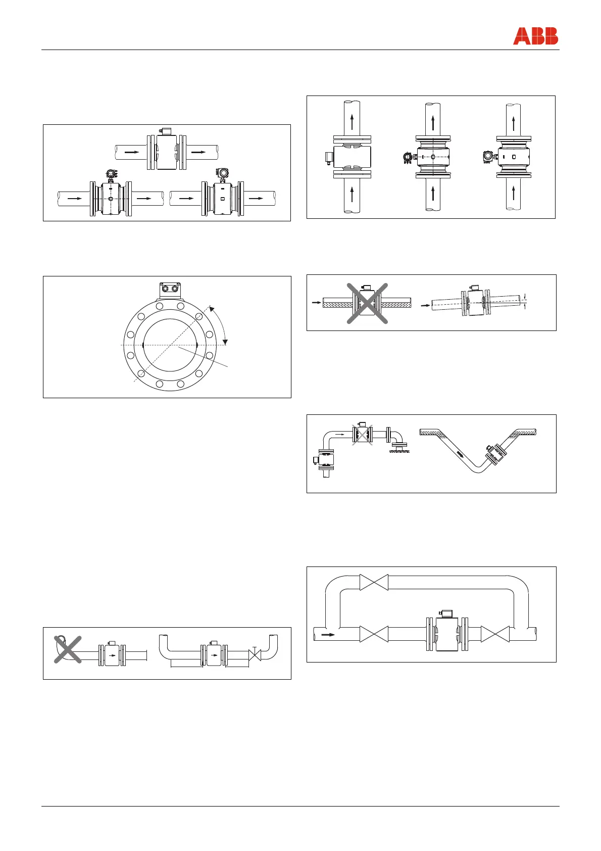
4.5.1 Flow direction
The device measures the flowrate in both directions. Forward flow is
the factory setting, as shown in Fig. 10.
G00657-01
Fig. 10
4.5.2 Electrode axis
Electrode axis (1) should be horizontal if at all possible or no more
that 45° from horizontal.
G00041
max. 45°
1
Fig. 11
4.5.3 In- and outlet pipe sections
The metering principle is independent of the flow profile as long as
standing eddies do not extend into the metering section, such as may
occur after double elbows (1), in the event of tangential inflow, or
where half-open gate valves are located upstream of the flowmeter
sensor.
In such cases, measures must be put in place to normalize the flow
profile.
• Do not install fittings, manifolds, valves, etc., directly in front of the
flowmeter sensor (1).
• Butterfly valves must be installed so that the valve plate does not
extend into the flowmeter sensor.
• Valves or other turn-off components should be installed in the
outlet pipe section (2).
Experience has shown that, in most installations, straight inlet
sections 3 x DN long and straight outlet sections 2 x DN long are
sufficient (DN = nominal diameter of the sensor Fig. 12 ).
For test stands, t
he reference conditions of 10 x DN straight inlet and
5 x DN straight outlet must be provided, in accordance with EN 29104
/ ISO 9104.
G00983
1
2
2xDN
3xDN
Fig. 12
4.5.4 Vertical connections
• Vertical installation for measuring abrasive fluids, preferably with
flow in upward direction.
G00039-01
Fig. 13
4.5.5 Horizontal connections
• Meter tube must always be completely full.
• Provide for a slight incline of the connection for degassing.
G00038
3°
Fig. 14
4.5.6 Free inlet or outlet
• Do not install the flowmeter at the highest point or in the draining-
off side of the pipeline, flowmeter runs empty, air bubbles can
form (1).
• Provide for a siphon fluid intake for free inlets or outlets so that
the pipeline is always full (2).
G00040
1
2
Fig. 15
4.5.7 Strongly contaminated fluids
• For strongly contaminated fluids, a bypass connection according
to the figure is recommended so that operation of the system can
continue to run without interruption the during the mechanical
cleaning.
G00042
Fig. 16

 Loading...